


For a power electronics system that is to serve an application in the 2 MW range, the question arose as to which technology should be used and what service life would result.
The available alternatives were classic semiconductor modules, constructed using solder-bond technology, and disc cells with the same power rating in press pack housings. Examples are displayed in Figures 1 and 2.

The expected service life is determined, among other things, by power cycling (PC). Current changes in the semiconductors cause temperature deviations in the assembly- and connection-technology. Thermal swings in the time range of a few seconds initially cause microscopically small movements of the bonding wires due to thermal expansion. In the long term, these lead to defects such as the bond connection lifting off or the bond wires breaking at the fastening point.
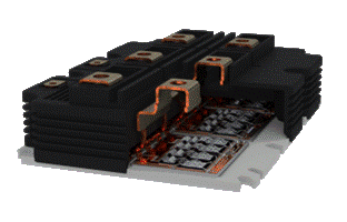
Figure 1: Power Semiconductor in solder-bond technology
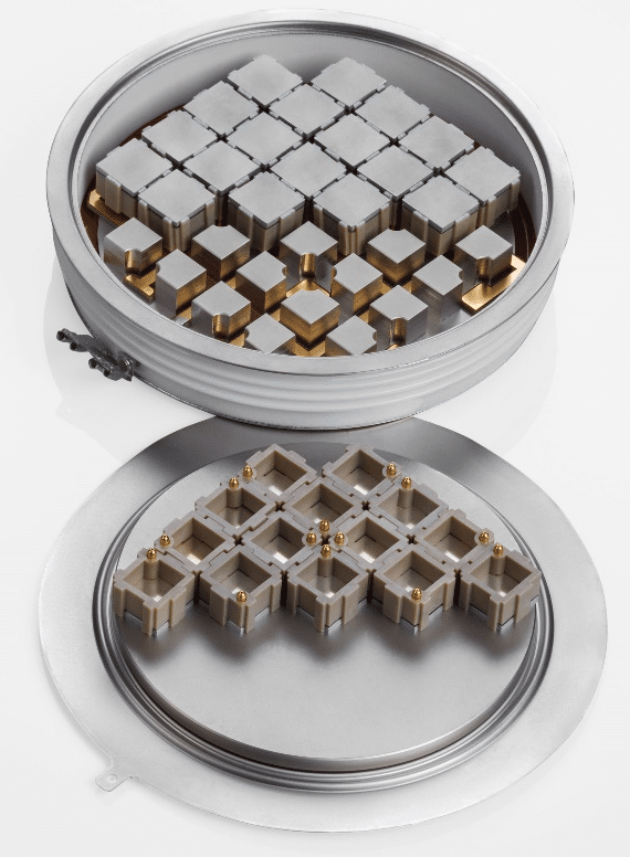
Figure 2: Press Pack IGBT
If the pulse duration is extended, the individual components in the structure heat up and different expansion coefficients lead to the development of mechanical stresses. In the long term, this also leads to disintegration of the bonding layers and delamination. In the end, the thermal contact resistance increases, and the component dies from heat.
Disk cells are constructed without bonding wires and large-area solder connections are also absent in this technology. The expectation is therefore that these components allow a significantly higher number of cycles than assemblies with a solder-bond structure.

However, the comparison of the corresponding curves in Figures 3 and 4 initially appears to refute this.
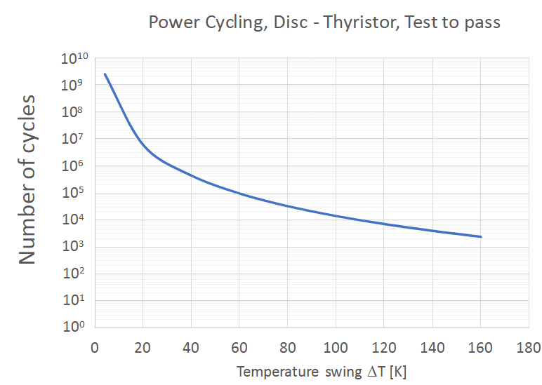
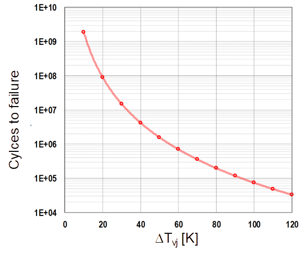
Looking at the number of cycles to be taken from the diagrams for a temperature range of 80 K, it reveals that the disk cell only survives 30,000 cycles, whereas the solder-bond module survives many times that number at 200,000 cycles.
So does the disk cell fail earlier?
Experience shows that this does not happen. There are systems equipped with disk cell thyristors that have been working for decades without failure.
Why don’t these curves reflect this?
Only at first glance do they not. If you delve deeper into the subject, you will also find the boundary conditions under which such tests are carried out.
Power cycling for solder-bond modules can be achieved by applying a pulse of 1.5 seconds duration. The small thermal capacities of the bond wires are thus served, and the desired temperature is reached on the actual chip. After the current is switched off, the semiconductor cools down again to the initial value within a further 1.5 seconds. A single cycle therefore only takes three seconds.
The thermal capacity of disk cells is given by the solid metal plates with which they are contacted. These copper disks, which often weigh several hundred grams, hardly heat up at all within seconds.
A typical cycle that heats the semiconductor to the desired temperature requires a switch-on time of three minutes, with cooling taking a further two minutes. The entire cycle therefore takes five minutes.
100,000 cycles at 80 K swing with the solder-bond technique therefore result in an operating or test duration of 300,000 seconds, which corresponds to 83 hours or just over three days.
In contrast, 100,000 cycles of five minutes each with disk cells represent 347 days of operation or testing.
Another detail is that the curve for disk cells shows “test to pass”. This is a routine test that ensures that the components meet this minimum requirement. It does not indicate that an end of life has been reached and 100% of all disk cells achieve this result.
In contrast, the PC curve for solder-bond modules shows “test to fail”, meaning that this technology has reached the end of its life at this number of cycles. In this case, the result is limited to 95% of the tested components in accordance with the standard specifications. A 100% curve is usually one magnitude below the curve for the end of life.
The PC curve for disk cells therefore makes an extremely conservative statement.
So why don’t manufacturers also supply a “test to fail” curve for disk cells?
It is known from experience that disk cells hardly suffer from power cycling and do not fail in the field due to this load. The “test to pass” curve is therefore certainly at least 2 magnitudes lower than the “test to fail” curve.
If the cells do not withstand 2000 cycles in the test even at temperature swings of 160 K but – two magnitudes higher – rather 200,000 cycles, this results in a test duration of one million minutes – or almost 700 days. Since at least two or three measuring points are required for a curve, additional tests would be necessary at temperature swings of 60 K and 100 K.
For a 60 K swing, the curve already shows 100,000 cycles. Just one decade more would mean one million cycles, 5 million minutes or almost 10 years in the test.
In addition, at least 1.5 kW of power is required for each cell in these tests, which amounts to a test power of no less than 30 kW.
Nevertheless, tests were initiated at high temperatures in order to reach the actual end of life, but this highlighted another difficulty.
The failure in the test did not affect the disc device – the test equipment itself failed due to power cycling long before the devices tested showed any damage.
What does this mean for the design?
In power electronics, power cycling is mainly considered in connection with failures of bond connections. This failure mechanism does not exist in disk cells. In addition, the large thermal capacities of the disk cell mean that the semiconductor heats up much slower, and the double-sided cooling also reduces the temperature swing for the same power.
In combination, the relieving effects mean that the classic “power cycling” failure mechanism has no life-limiting influence on disk devices. This is also one of the reasons why this design is used in railroad applications, marine propulsion systems and electrolysis plants, where an operating life of up to 160,000 operating hours in 20 years is expected.
Author: Dr. Martin Schulz joined Littelfuse in February 2021 as Global Principal in Application Engineering. He is responsible for power semiconductors for electric commercial vehicles, charging infrastructure, energy storage systems and industrial drive technology. He is an expert in packaging and interconnect technology in power semiconductors as well as in thermal management of power semiconductors. Martin Schulz has more than 20 years of experience in the field of power electronics and is a Senior IEEE-Member.