


Strict legal regulations and growing customer interest in safety applications that protect drivers and reduce accidents are driving the demand for driver assistance systems. In addition, reliability is becoming increasingly important to meet the ISO 26262 standard for functional safety in automotive electronics. Passive components that are mechanically robust and can withstand sudden temperature fluctuations are required for automotive applications. These include multi-layer ceramic chip capacitors (MLCCs), inductors for decoupling and power supply circuits, and chip beads for signal and power supply lines.
In order to meet these safety requirements, components with plastic electrodes—which are also known as “soft termination”—are used to reduce two common sources of error: bending and soldering cracks. In this blog, we explain how these errors can be avoided by “soft termination.”

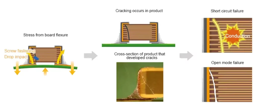
Main Causes of Flex Cracks
Flex cracks are caused by excessive deflection of the circuit board. This can occur during the manufacturing process, e.g., B. by soldering voltage due to too much solder, or by tension during desoldering or screwing. Flex cracks can also occur during final assembly and operation when the circuit board is subject to constant vibration.
MLCCs and ferrite components tend to be robust when under pressure but weaker under stress. This difference is partly due to the brittle nature of ceramics. When subjected to tensile stress, unlike metals, they cannot yield and relieve stress. Therefore, a soldered component can easily crack if it bends too much.
Avoidance of Flex Cracks
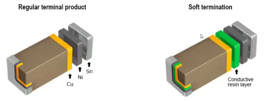
The terminal electrode of a conventional MLCC has the lower copper (Cu) layer electroplated with nickel (Ni) and tin (Sn). A conductive resin layer between the Cu and Ni layers creates a flexible connection (soft termination). This resin layer reduces the stresses caused by expansion or contraction of the solder joints due to temperature changes or bending stresses on the circuit board, causing cracks in the capacitor element.
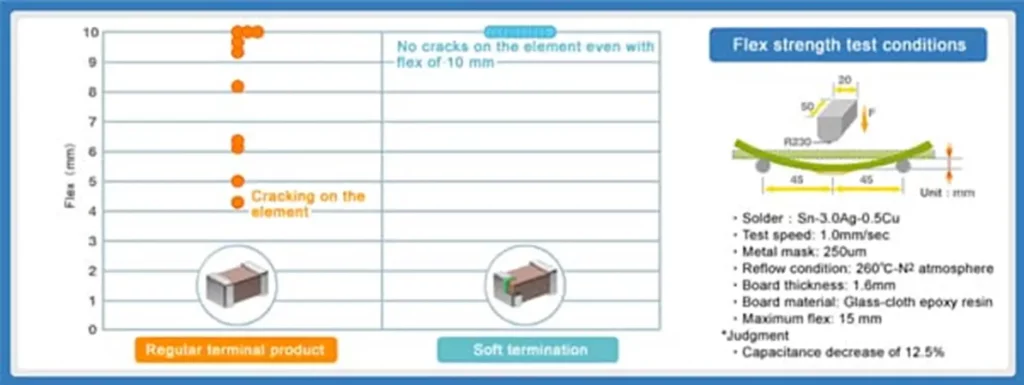
A comparison of the flexural strength shows that the standard product begins to crack at around 4mm of deflection. In contrast, soft termination products do not crack even when subjected to a bending stress of more than 10mm. Although the nickel layer and the conductive resin layer peeled off, cracks in the ceramic body were prevented.
Taking this a step further, safety in battery-power supply lines can be significantly improved by replacing a traditional MLCC with a dual-safety MLCC. Dual-safety design MLCCs offer the highest protection against cracks and short circuits. First, the conductive resin is layered in the terminal electrodes to prevent cracking. On the other hand, the inner electrodes have a special structure that corresponds to a series connection of two capacitors. This structure reduces the risk of short circuits even if a crack occurs on the capacitor element. Because a single MLCC in series meets AEC-Q200 safety requirements, thus eliminating the need to daisy chain two standard MLCCs.
Similar to conventional inductors and chip beads, the silver electrode (Ag) is coated with Ni and Sn on the underside. A shatterproof connection is achieved by applying a conductive resin layer between the Ag and Ni layers.
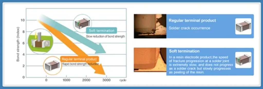
In comparative tests, multi-layer inductors and chip beads with resin electrodes have demonstrated almost twice the flexural strength (critical deflection) of products with conventional electrodes. With conventional products, cracks appear on the ceramic element at a bend of about 4mm. Soft termination products, on the other hand, can withstand a 7mm bend.
Main Causes of Thermal Cracks in Solder Joints
Cracks in solder joints are primarily caused by thermal fatigue due to thermal shock or thermal cycling and/or the use of lead-free solder, which is more brittle than leaded solder. Therefore, special care should be taken when mounting passive components near strong heat sources where sudden temperature changes (temperature shock) can occur.
If a solder joint is repeatedly thermally stressed, the different thermal expansion coefficient (CTE) of the passive component and the circuit board can lead to cracks in the solder. This can also occur if there is insufficient temperature control during the soldering process.
Other Improvements in Soft Termination Products
Soft termination products have a conductive resin layer inside the terminals to reduce mechanical stress. However, this layer causes additional resistance, which also affects the ESR characteristics. To compensate for this disadvantage, TDK introduced a new type of soft termination products. The CNA series MLCCs feature a wide terminal electrode on the PCB mounting side. The material components of the connections are the same as with conventional soft termination products. However, the resin layer is applied only in the risk areas on the PCB assembly side. This provides effective stress relief as the entire connector area is not covered with resin.
Conclusion
Thanks to the improved robustness of soft termination products, the effects of bending stresses and temperature fluctuations on the circuit board can be suppressed, increasing the reliability of the connections. For more information on TDK Soft Termination MLCCs, see C Series Soft Termination MLCCs and CNA Series MLCCs.
Author: Mouser Electronics
