The term bench brings about a mental image of a DC power supply used on an engineer’s or a technician’s bench for innumerable power tasks. These might be variable DC bench power supplies that appear to be relatively simple instruments, but engineers rely on these to deliver stable, precise and clean voltages and currents, regardless of load.
To identify the appropriate bench power supply for a particular application, one must come up with answers to several important questions and understand the basics of how power supplies are specified. We have to consider the following points to save substantial time and money later in the system configuration process.

Power, voltage and current requirements for device under test
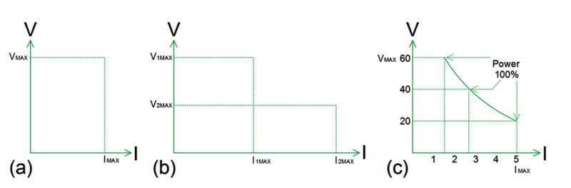
Different types of power supplies can have different power envelopes (Figs 1a, b and c). In a rectangular power envelope type of supply, any load current can be supplied at any voltage level.
Another type has multiple rectangular envelopes for multiple ranges that offer the option of higher values of one parameter at the expense of the other.
Then there are those that can deliver a hyperbolic envelope that provides a more continuous transition than multi-range power supplies. In this kind of supply, one parameter is inversely proportional to the other.
High-power output supplies tend to have either a multi-range or a hyperbolic envelope. To make the right selection, take the time to evaluate the power levels required by the application.
Parameters to be considered
Although many key power supply parameters will vary depending on each application, following parameters are critical in all cases:
Accuracy. It determines how close the regulated parameter is to its theoretical value. Output uncertainty is largely due to error terms in case of a digital-to-analogue converter (DAC). Setting accuracy is tested by measuring the regulated variable with a traceable, precision measurement system connected to the power supply’s output. It is given as ±(% of setting + offset).
Resolution. It is the smallest change in voltage or current settings that can be selected on the power supply. The resolution specification limits the number of settable discrete levels. A DAC with more bits produces finer resolution. But, with corrections for offset and gain errors, resolution will be less than the number of bits in the DAC. Setting resolution may be expressed as an absolute unit value or as a percentage of full scale.
Readback accuracy. It determines how close the internally-measured values are to the theoretical value of the output voltage (after setting accuracy is applied).
Readback resolution. It is the smallest change in internally-measured output voltage or current that is discernible by the power supply. It is usually expressed as an absolute value, but can also be given as a percentage of full scale.
Stability. A power supply’s performance inevitably changes due to aging. Maintaining long-term stability demands regular verification and calibration.
Temperature stability. Power supply accuracy is usually specified over a temperature range, often between 20°C and 30°C.
Load regulation. It is a measure of the ability of the output voltage or output current to remain constant during changes in the load. This familiar format is easy to understand and verifiable through testing. It is given as ±(% of setting + offset).
Line regulation. It is a measure of the ability of the power supply to maintain its output voltage or output current while its AC line input voltage and frequency vary over the full allowable range. This offers a worst-case picture, which is given as ± (% of setting+ offset).
Direct-current power supplies do not actually produce perfect DC outputs. Output AC noise and transient response change both load and settings. Some of the AC characteristics are described below.
Ripple and noise. Spurious AC components on the output of a DC supply are also often referred to as periodic and random deviation (PARD).The term ripple refers to periodic AC on the output. When viewed in frequency domain, ripple shows up as spurious responses. Unlike ripple, noise is random. Noise covers a broad spectrum, and when viewed in frequency domain, manifests itself as an increase in the baseline.
Transient response. It is tested by applying significant step changes to load impedance and power supply settings, and measuring the time to settle to a stable DC value.
Required output accuracy level
It is important to review the power supply’s output accuracy and read-back specifications in case of accurate control of voltage at the load for research experimentation or device characterisation.
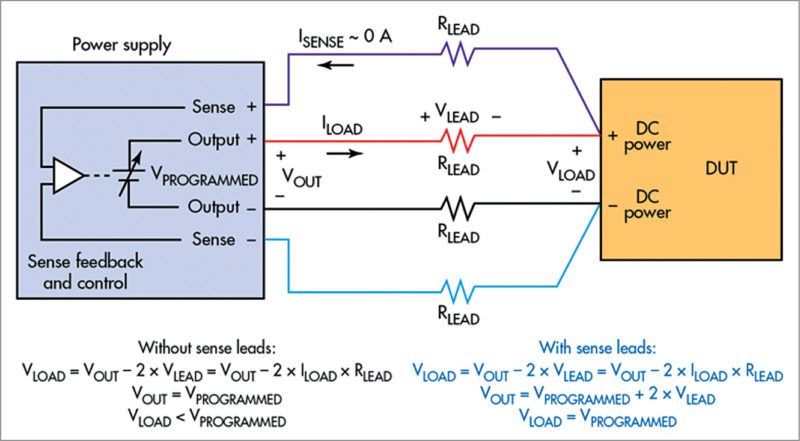
Programmable power supplies are equipped with remote sense capability. Remote sensing is required in applications where load is located at some distance, typically >3m (10-feet) from the power supply output terminals. It solves the problem of voltage drop in the leads by extending the power-supply feedback loop to the input of the load.
The difference in voltage is based on the amount of current and the load lead size and length. It uses a 4-wire connection (Fig. 2) to make sure the voltage you set on the supply is the voltage you get at the device under test (DUT) despite voltage drop in cables that carry current between the power supply and DUT.
Acceptable maximum level of noise in the supply’s output
For powering a very low-voltage circuit, or a circuit that uses or measures very low currents, such as a transducer detector that must pick up millivolt or microampere signals, noise from external sources may cause problems.
The power supply itself is a noise source. This noise breaks down into two components: normal mode and common mode. Normal-mode noise, which is generated across the power supply’s output terminals, exudes from the power supply’s internal circuitry.
Common-mode noise is Earth-referenced noise originating from the power line and stray capacitance across the main transformer.
Two types of bench DC power supplies are commonly used today, namely, linear and switch-mode.
Linear supplies are simple and heavier because the 50Hz or 60Hz transformer and associated filters are physically larger. The linear topology generates minimum noise on the power supply’s output.
Switch-mode power supplies (SMPS) are significantly smaller, lighter and more efficient than linear power supplies, so these have replaced linear supplies for higher power requirements.
On the negative side, high switching frequency of SMPS generates five to ten times more noise than a linear supply. Whenever it commands minimising noise, choose a linear supply (if one is available) based on power requirements.
Number of outputs required
In many cases, a single output will be sufficient; however, multi-output supplies can sometimes deliver several important advantages.
Triple-output power supplies typically contain two higher-voltage outputs for analogue circuits (to power multi-voltage circuits or to create bipolar power supplies for testing bipolar analogue circuits) and a third output intended to power a digital circuit. For greatest flexibility, make sure that all three outputs are programmable.
If the DUT requires individual isolated power supply sections, a decision must be made to either configure multiple isolated supplies or buy a multi-output supply. The catch is that multi-output supplies can either have isolated outputs or output channels tied to a common point on their low side. When outputs are connected to the same common point, these are not suitable to power circuits that are isolated from each other.
For applications that require powering circuits up and down in a specific sequence, a multi-output supply with independently controllable outputs is usually better than a set of individual supplies.
For applications that require sourcing of more voltage or current beyond a single output’s capability, some multi-output power supplies allow outputs to be combined in series or in parallel. Non-isolated multi-output power supplies cannot parallel the two outputs. To ensure flexibility, look for a multi-output power supply with isolated outputs.
Interfaces needed
There have been numerous types of computer interfaces over the years with instrumentation. Two of the most popular have been IEEE-488, also known as general-purpose interface bus (GPIB), and RS232 serial communications. Network interfaces (for example, Ethernet) and USB interfaces have also been used.
One question to consider is: Would a digital I/O interface make it easier to generate fault status outputs or control an external relay or status lamp?
Placement of output connectors
Front-panel connections simplify frequent access and are more common with bench power supplies. Rear-panel connectors are generally considered superior for rack based automated test systems—these rarely require changes after setup. However, more manufacturers now offer power supplies equipped with both front- and rear-panel connections. This simplifies transition from bench experimentation to high-speed automated testing, because the same power supply suits both environments.
DIY bench power supply
A good power supply is very useful when working with electronics, but it can be costly. Any ATX (Advanced Technology eXtended) power supply can be plugged into the adaptor and can output 3.3V, 5V, 12V and -12V. (ATX is a motherboard developed by Intel in 1995 to improve on previous de facto standards.) It can be converted into a variable bench power supply. You can add female headers and banana jack (for appliances that draw more current) as output, or even a USB port.
For powering some DC motors, you can add variable output with an LM317, controlled by a potmeter. Although an ATX power supply should have a short-circuit protection built in, you can add output fuses as a safety measure. Make a case with plexiglass as it is nice to see the cable management inside.
In the same way you can combine LTC3780, which is a powerful 130W step-up/step-down converter, with a 12V 5A power supply to create an adjustable lab bench power supply in the range of 0.8V-29.4V and 0.3A-5A approximately.
You may add any standard make microcontroller and LCD to make it look like a modern power supply.
The future
Design and validation engineers need to power their DUTs safely and easily during manual tests or automated sequences. They are frequently under pressure to perform tests quickly, and their test benches are often crowded.
“Our customers told us they want a Keysight-quality bench power supply with modern I/O, a compact footprint and excellent bench usability,” says Kari Fauber, general manager, Keysight’s Power and Energy Division. “We built the E36100 series to meet the needs of R&D and design validation engineers who face increasing pressures to produce high-quality designs quickly and who want to power their devices with confidence,” he adds.
The E36100 series adds five new models with up to 100V or 5A output to Keysight’s extensive portfolio of bench power supplies. Its compact form factor (2U, ¼-rack) saves space on the bench or in the rack, and standard LAN (LXI Core) and USB interfaces make it easy to connect the power supplies to a computer. An intuitive onscreen menu system makes it easy for engineers to perform manual tasks quickly, and over-voltage and over-current detection helps them protect their DUTs.
E36100 series models come standard with measurement capability for very small currents, a high-contrast OLED display that makes it easy to view the screen from anywhere, even from sharp angles, support for BenchVue software, IVI drivers and SCPI commands, three-year warranty and Keysight’s worldwide support.
PeakTech’s newly-developed, linear-regulated dual-channel laboratory power supply (2 x 0-30V/0-5A DC/5V/1A fixed) with a modern design and the latest technology is provided with a blue LED display for fast and accurate reading of voltage and current values. Output voltage and current limit for the main channels are each continuously variable and can be connected independently from each other in series or parallel mode. Thus, with outputs connected in series, the maximum output voltage rises to 60V DC and outputs connected in parallel double the maximum output current to 10A DC. This device combines easy handling and high efficiency to offer universal applications in research, development, electrical engineering or training.
Biswajit Das is manager-R&D, EFY Labs