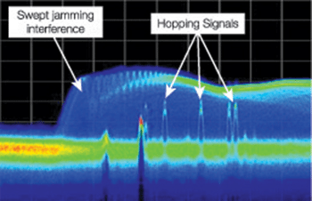
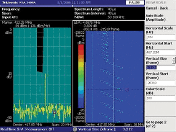
The erratic behaviour of frequency-hopped signals makes them difficult to capture, verify and measure. Hence more effective tools and processes are required to design and test modern radios that employ increasingly fast frequency-hopping techniques
NARESH NARASIMHAN
JULY 2009: Designers have long sought to improve the performance and resiliency of radio communications. With the radio frequency (RF) spectrum becoming more crowded and interference more prevalent in recent years, these efforts have become increasingly critical.
Several techniques are now being utilised to ensure efficient communications across the jam-packed radio spectrum. Chief among them are software-defined radios (SDRs), which enable software to dynamically control communications parameters such as the frequency band used, modulation type, data rates and frequency-hopping schemes.
Military radio applications, which must perform in mission-critical environments where malicious signal jamming is common, frequently employ SDR technologies. They can be found in a wide range of footprints, from compact, portable units to vehicle-mounted and shipboard platforms. A number of commercial applications, such as wireless local-area networks (WLANs) and 3G-based cellular communications, have also surfaced recently that employ many of the SDR technologies first used by the defence electronics industry.

Despite the wide variety of SDR applications and footprints, one trait is common among them: frequency hopping. Employed in analogue as well as digital radios, frequency hopping is used to improve performance, avoid detection and mitigate jamming and interference, such as multipath and fading.
Frequency hopping is utilised in conjunction with coding schemes, which improve the ability to recover from interference and fading, to spread the information over a wide spectrum of frequencies, making systems more robust. If a particular frequency is jammed, the system may lose only the information being transmitted at that frequency, rather than an entire data stream. In these circumstances, interleaving and forward error correction (FEC) can be used to recover data lost during the jammed hop.
While frequency hopping is a proven method for improving radio communications, its use continues to evolve. The faster a signal hops, the less likely it is to face detection, interference or jamming. So although frequency hopping is not a new technique, designers are continually striving to increase the speed of frequency hopping in modern radios to further improve and reinforce performance.
These efforts have led to notable design and test challenges. Frequency-hopped signals and interference sources operate in extremely complex, time-varying spectrums. The erratic behaviour of these signals can make them difficult to acquire, verify and measure. Effectively designing and testing modern radios that employ increasingly fast frequency-hopping techniques requires new tools and methodologies.
Faster hopping leads to new design and test challenges
Faster frequency hopping poses a number of challenges when designing communication systems, especially the system architecture and frequency synthesisers. Modern radios are complex systems, and the controlling software, digital signal processor (DSP) and system components all must work in concert to ensure optimal performance. Because software actively alters SDR operating parameters, there are countless hardware/software combinations that can cause errors. Modulation and filtering transients, distortion, non-linear power effects, pulse aberrations, frequency tuning and settling, power supply coupling, digital to RF couplings, and software-dependent phase errors are also common.
Designing fast frequency synthesisers presents a significant challenge as well. For example, a joint tactical information distribution system (JTIDS) deployed by the US armed forces working in an L-Band TDMA network operates at 38,461.5 hops per second. This means the frequency synthesiser has to hop from one frequency to the next, settle and communicate in less than 26µs time; system transient responses must be settled in just a few hundred nanoseconds to enable error-free communication.

Impaired modulation quality due to frequency settling of hopped carriers is one of the primary sources for poor transmitter quality and low system data rates. In the past, designers were able to use conventional test equipment to demodulate stationary carriers located at the centre frequency of their modulation analyser. However, conventional test equipment are not capable of demodulating today’s wideband hopped signals. Because these signals hop over the band of operation, analyses of off-centre frequencies are required to ensure optimal modulation quality.


