


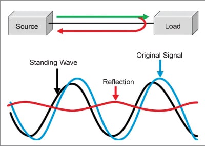
The return loss of signal and voltage standing wave ratio (VSWR) are two of the most important characteristics of an antenna. So, their proper understanding is essential for a good antenna design.
Antenna plays a major role at present in all fields of wireless communication. Return loss and VSWR are the two major indices to measure the input characteristics performance of the good antenna and any RF circuits in general as a network, which can be measured using a network analyzer.

We previously discussed Antenna Gain and Directivity. Now let’s understand the importance of return loss and VSWR in Antenna Design.
Return loss is the parameter that indicates the portion of power rejected and returned to any source that intended to transmit it. It represents the percentage of impedance matching between the two points (source and load) in power transmission in terms of the portion of power reflected back to the source from the load. The higher the impedance matching, the lesser will be the return loss.
Antenna Return Loss (R)
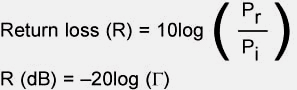
Generally, the return loss can be defined as the amount of power returned or reflected due to discontinuity in the path of transmission or the impedance mismatch, which will also be detailed here. It is the ratio of incident or input power (Pi) to the reflected or return power (Pr) measured in decibels (dB).
Return loss can be related to the reflection coefficient and voltage standing wave ratio (VSWR). The reflection coefficient is the ratio of incident or forwards voltage to output or reflected voltage represented by Γ and related to return loss as follows:
Impedance (Z)
Fig. 2 shows the three components involved in radio transmission, that is, the source to transmit radio signals, the transmission line, and the antenna as the load. The figure shows the matched and mismatched conditions.
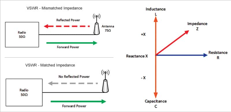
This classification is based on the difference between the numbers in the figures indicated near the radio (50Ω) and antenna (75Ω). These numbers represent the impedance (Z) of the concerned device, which is complex in nature and is a combination of resistance (R) and inductive reactance (L) or/and capacitive reactance (C).
Remember that the value of impedance depends on the frequency of operation.
Voltage Standing Wave Ratio (VSWR)
VSWR indicates how well the source or load is matched in impedance with the antenna and the transmission line used for power transmission. It represents the maximum and minimum voltage level along the entire length of the transmission line as follows:
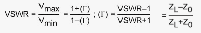
ZL and Zo are the load and characteristics impedance of the transmission line.
When there is a proper impedance match between the source and the load, there is no reflection, and hence Γ=0, and thereby VSWR is the positive and real number with minimum and maximum values of 1 and infinity, respectively. Hence for a perfectly tuned antenna, the VSWR should be 1 to indicate that no power is reflected back to the source.
More the VSWR, the higher will be the loss and the lesser the power transmission efficiency.
For good real-time RF components, VSWR lower than 1.5:1 has to be considered for the typical impedance value of the transmission line, which is from 50Ω to 75Ω. The return loss, reflection coefficient, VSWR, and percentage of power reflected are related as shown in Table 1.
| Table 1: | ||||
| Relationship Between Antenna Return Loss, Reflection Coefficient, VSWR, and Power % Reflected Back | ||||
| VSWR | Reflection Coefficient | Return Loss (dB) | % of Reflected Power | Meaning |
| Infinite | 1 | 0 | 100 | No power transmitted and all reflected (short or open circuit) |
| 17 | 0.84 | 1 | 80 | 80% reflection and 20% transmission |
| 6 | 0.44 | 3 | 50 | 50% reflection and 50% transmission A good rule of thumb: 3:1=6dB |
| 2 | 0.32 | 10 | 10 | 10% reflection and 90% transmission A good rule of thumb: 1.5:1=14dB |
| 1 | 0 | Infinite | 0 | 0% reflection and 100% transmission are a perfect match |
| Table 2: | |
| Comparison between Antenna Return Loss and VSWR | |
| VSWR | Return Loss (RL) |
| Ratio of voltage applied to voltage reflected | Portion of a signal reflected due to discontinuity in line to indicate the loss |
| Preferred in the connector industry | Preferred in the cable industry |
| It is a linear measurement | It is a logarithmic measurement |
| Useful when displaying larger reflections | Useful when displaying very small reflections |
| VSWR=(1+10RL/20)/(10RL/20-1) | Return Loss=20 * Log10 (VSWR+1/VSWR-1) |
From the table we can understand that when the return loss is <10dB, the antenna will be at VSWR >2, indicating the system will reflect >30% power and the performance of the antenna will be <70%.
For VSWR=2, reflection coefficient will be=1/3 and 20log(1/3) =-9.54dB.
Therefore, a VSWR of less than 1.5:1 is considered ideal in the RF field, and a VSWR of 2:1 is marginally acceptable for more critical loss systems for low-power applications.
We have designed a special VSWR and Return Loss Calculator. You can use it for free.
Dr. S. Suganthi is a Professor at the ECE Department, K. Ramakrishnan College of Technology, Samayapuram, Trichy