


A power supply configuration that achieves this is shown in Fig. 12. As shown in the figure, there are two current-sense loops controlled by the same reference voltage. Another possible approach could be to use a precision reference for one arm and then use the actual controlled current flowing through that arm as the reference for controlling current in the other arm. The preferred circuit topology for the power supply is an externally-driven PWM-controlled fly-back converter generating a regulated output voltage equal to the sustaining voltage at the required plasma current.
Carbon dioxide laser power supplies
Carbon dioxide (CO2) lasers are operated in both CW and pulsed-output modes. CW lasers are either DC-excited or RF-excited. Pulsed-output lasers are mainly transversely-excited atmospheric-pressure (TEA) lasers. Power supply circuits for DC-excited lasers are similar to the ones described in earlier paragraphs in the case of helium-neon lasers. Different power supply circuits discussed in the case of helium-neon lasers are equally valid for carbon dioxide lasers.

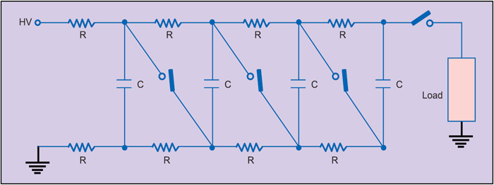
Present-day TEA CO2 lasers use Marx bank capacitor systems. In this system, the arrangement of individual capacitors is such that they are in parallel during the charging process and in series during the discharge operation. This means, if each capacitor in the bank were charged to a voltage V, then the total voltage available across the tube for discharge operation would be nV, n being the number of capacitors.
Fig. 13 shows the Marx bank power supply arrangement where the switches are open during the charging. They are triggered simultaneously to the closed position to initiate discharge. Though the Marx bank shown here uses four stages, Marx bank systems with higher number of stages are also used. Marx banks are particularly suitable for producing fast-rising pulses.
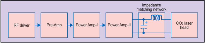
Power supply of an RF-excited CO2 laser comprises an RF source and an impedance-matching network (Fig. 14). The RF source may further be split up into an RF oscillator and a cascade arrangement of RF amplifiers, depending upon the output power delivering capability. Frequency of operation is in the range of 50MHz to 150MHz. RF power is fed to the laser cavity through impedance-matching network. The laser cavity’s mechanical structure combined with RF discharge can be considered as an electrical load comprising complex impedance. Power transfer efficiency from the RF source to the discharge is a key operational feature of the laser that is made more complicated by the fact that the discharge impedance is power dependent.

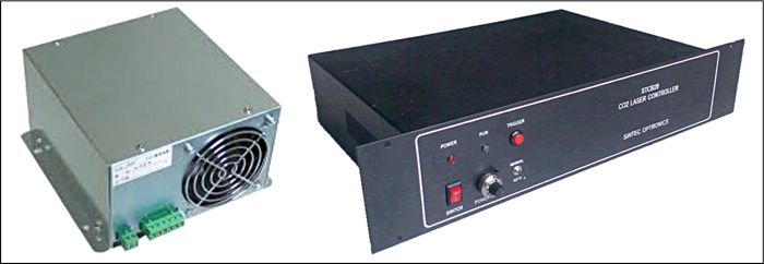
CO2 laser power supplies too are commercially available both as bench-top laboratory systems as well as compact versions for OEM market (Fig. 15).
Frequency stabilisation of lasers
Carbon dioxide and helium-neon lasers have Doppler broadened gain versus frequency curves, which is 60MHz in the case of carbon dioxide laser and 1400MHz for helium-neon laser emitting at 632.8nm. With active stabilisation techniques, such as dither stabilisation, optogalvanic stabilisation and stark cell stabilisation, these lasers can be frequency stabilised up to an accuracy of ±1MHz.
Fig. 16 shows block diagram of dither stabilisation scheme. The grating allows selection of various lines within the laser tuning curve. The output of the low-frequency oscillator, when applied to the PZT, moves the grating along the axis and hence varies the output. The other input to the frequency synchronous detector is the error signal, which corresponds to the deviation in the laser output frequency from the line centre.
In fact, the magnitude and phase of the error signal determine the location of operational point with respect to the centre of the Doppler broadened gain curve. While the amplitude decides how far or close to the line centre the operational point is, the phase decides which side of the line centre it is located. Though Dither stabilisation is simple to implement, the disadvantage of this technique is the presence of frequency modulation in the output as a result of laser dithering.
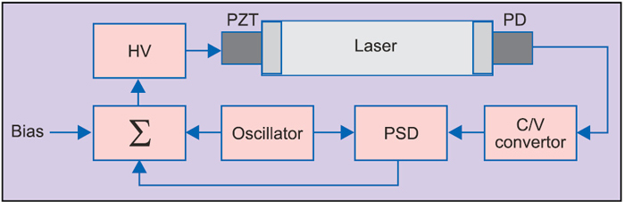
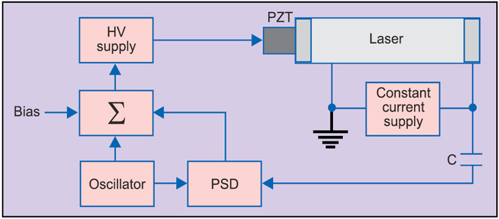
Optogalvanic stabilisation technique is particularly suitable for carbon dioxide lasers. It makes use of variation in discharge impedance due to alteration in internal radiation field intensity. Fig. 17 shows a typical optogalvanic frequency stabilisation set up.
An AC signal is applied to the cavity length transducer resulting in frequency modulation of the laser and therefore modulation of the plasma-tube impedance. The impedance variation, which is proportional to the slope of the output power versus frequency curve of the laser, is measured by exciting the plasma-tube by a high-speed current-regulated power supply and measuring the resulting variation in voltage-drop across the plasma-tube. This voltage is applied to the synchronous detector. The other input to the synchronous detector is the reference signal used to modulate the laser cavity length with the help of PZT. The error signal produced at the output of synchronous detector is used to stabilise the laser frequency.
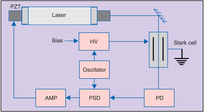
Stark cell stabilisation technique allows dither-free frequency stabilisation. It also allows stabilising frequency anywhere on the Doppler broadened gain versus frequency curve of the lasers. Fig. 18 shows the block diagram of stark cell stabilisation.
A part of the output laser beam is made to pass through the stark cell. An appropriate value of DC voltage is applied to one of the stark plates to make the stark-shifted molecular transition of the gas contained in the cell precisely coincide with the carbon dioxide laser output line of interest. A slowly varying linear voltage ramp may be applied instead. Also superimposed on this is a relatively high-frequency sinusoidal or square waveform. The frequency is 5kHz, typically. The beam at the output of the stark cell is thus modulated in both amplitude and frequency by the applied high-frequency signal around the line of interest.
The laser beam is phase-sensitively detected with high-frequency signal applied to the stark cell as reference. The output of phase-sensitive detector is the frequency-discriminant error signal. The error signal is amplified and then fed back to the PZT through a suitable interface. One of the end elements of the cavity is mounted on the PZT. The error signal adjusts the length of the cavity in the feedback mode to lock the laser frequency to the centre of the Doppler profile of the line of interest.
With this article, the four-part series focussing on the role of electronics in military lasers and optoelectronics is completed. While introduction to role of electronics, solid state laser electronics and semiconductor diode laser electronics were discussed in the earlier parts, important building blocks of electronics used in common gas lasers are discussed in this concluding part. Different circuit topologies in use for design of power supplies for carbon dioxide and helium neon lasers have been discussed at length, highlighting important design-related issues with reference to gas lasers for military applications. Different techniques of frequency stabilisation of gas lasers, which is of paramount importance in applications such as laser radar, have also been covered.
Dr Anil Kumar Maini is a senior scientist, currently director of Laser Science and Technology Centre, DRDO, Ministry of Defence, while Nakul Maini is technical editor with Wiley India Pvt Ltd
