Carbon dioxide laser-based range finders and laser radar and helium-neon laser-cavity-based ring-laser gyroscope inertial navigation sensors are among the common military applications exploiting use of gas lasers. In addition, such gas lasers as gas dynamic carbon dioxide lasers, chemical oxy-iodine lasers, all gas-phase iodine lasers, hydrogen fluoride and deuterium fluoride lasers, though not electrically or optically pumped, these are largely exploited to build high-power directed-energy weapons. We shall, however, confine our discussion in this article to electrically-excited gas lasers having military applications.


In both carbon dioxide and helium-neon lasers, the power supply used to initiate and subsequently sustain electrical discharge through the gas mixture contained in a sealed envelope constitutes the primary and essential component of electronics. The active medium is usually excited either by passing an electric discharge current along the length of the tube known as longitudinal excitation in both types of gas lasers (Fig. 1), or by an electric discharge perpendicular to the length of the laser tube known as transverse excitation which is common in carbon dioxide lasers only (Fig. 2). Frequency-stabilisation electronics used in the case of actively-stabilised Doppler broadened gas lasers, such as helium-neon and carbon dioxide, is another area that relates to gas laser electronics.
Negative resistance characteristics
Gas-discharge characteristics, when excited electrically, are the key to design of power supplies for gas lasers. Typical gas-discharge characteristics, as applicable to carbon dioxide and helium-neon lasers, exhibit negative resistance in their current-voltage relationship. The current is zero initially, which may rise to a few nano amperes after the applied voltage exceeds a certain threshold causing some ionisation of the gas mixture. This current increases slowly till it reaches the breakdown point. At the breakdown point, large number of molecules in the gas mixture are ionised and conductivity increases significantly. Increase in discharge current causes further reduction in discharge resistance with the result that the voltage required to sustain the discharge actually decreases with increase in current. This gives rise to what is called negative resistance region in the gas-discharge current-voltage characteristics.
Helium-neon power supplies
The generalised form of a gas-laser power supply essentially comprises a high-voltage generation circuit that provides the starting voltage, either in the form of a high-voltage trigger pulse or a DC voltage level, to initiate the gas discharge, and a power supply with current-limiting feature to deliver the steady-state current to sustain the discharge. Amplitude of high-voltage trigger pulse needs to be greater than the breakdown voltage of the gas mixture in question. The current-limiting feature is provided by a resistance called ballast resistance, which limits the discharge current to desired value.
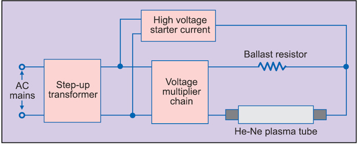
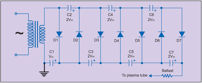
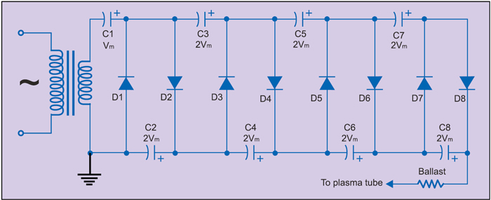
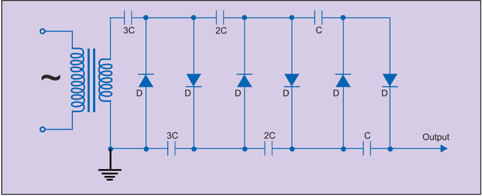
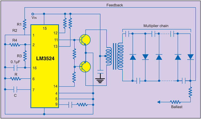
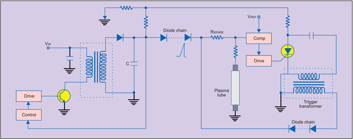
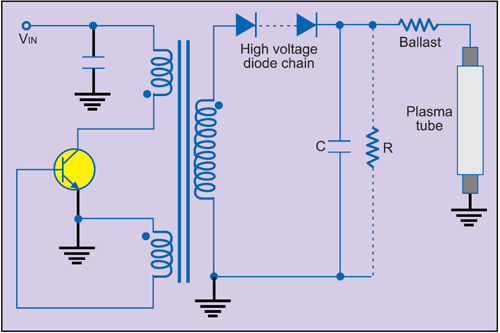
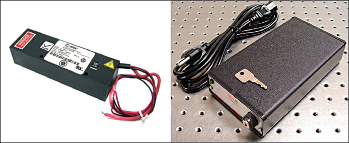
There are three commonly-used circuit topologies for designing helium-neon laser power supplies. In one of the topologies, an AC-DC or DC-DC (in case of portable systems) power supply producing an output voltage slightly higher than the voltage required to sustain the discharge plasma is cascaded to a voltage multiplier chain of diodes and capacitors to produce the starting voltage. The voltage at the output of multiplier chain drops to almost the voltage level present at the output of DC power supply due to inherently poor regulation of the multiplier chain.
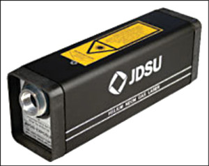
In the second commonly used circuit topology, the DC power supply is connected directly to the plasma tube through the ballast resistance. A high-voltage trigger pulse of 10-15kV is applied to the tube to initiate the discharge. Once gas mixture is ionised, the DC power supply takes over to sustain the discharge.


