


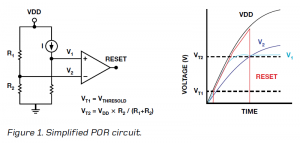
The power-on reset (POR) circuit included in many integrated circuits (ICs) guarantees that the analogue and digital blocks initialise in a known state after the power supply is applied. The basic POR function generates an internal reset pulse to avoid race conditions and keep the device static until the supply voltage reaches a threshold that guarantees correct operation. Note that this threshold voltage is not the same as the minimum power-supply voltage shown in the data sheet. Once the supply reaches the threshold voltage, the POR circuit releases the internal reset signal and the state machine initialises the device. Until initialisation is complete, the device should ignore external signals, including transmitted data. The only exception is the reset pin, which, if included, would be internally gated with the POR signal. A POR circuit can be represented as a window comparator, as shown in Figure 1. The comparator level, VT2, is defined during the circuit design depending on the device’s operational voltage and process geometry.

POR Strategy
The comparator window is typically defined by the digital supply level. The digital block controls the analogue block, and the voltage required for the digital block to be fully-functional is similar to the minimum voltage required for the analogue block to function, as shown in Figure 2.
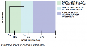
A higher threshold for VT2 is better for the analogue block, but making it too close to the minimum recommended supply voltage could inadvertently trigger a reset if the voltage drops slightly. If the device includes separate analogue and digital supplies, a strategy to avoid malfunctions is to add a second POR circuit that keeps both blocks reset until the supply voltage is high enough to ensure functionality. For example, in a 3V IC process, VT1 ≈ 0.8V and VT2 ≈ 1.6V.
These voltages can change depending on the process and other design variations, but these are reasonable approximations. The threshold tolerance can be 20 per cent or more; some old designs had up to 40 per cent tolerance. The high tolerance is related to power consumption. The POR must be enabled all the time, so the ever-present trade-off between accuracy and power consumption is important, as higher accuracy will make the circuit dissipate more power in standby mode without making a real difference in functionality.
Brownout Detector
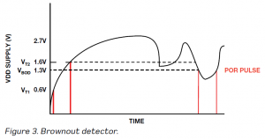
The POR circuit sometimes integrates a brownout detector (BOD), which avoids malfunction by preventing a reset if the voltage drops unexpectedly for only a short time. From a practical perspective, the brownout circuit adds hysteresis, typically around 300mV, to the threshold voltages defined in the POR block. The BOD guarantees that once the supply falls above VT2, the POR will not generate a reset pulse unless the supply drops below a different threshold, VBOD, as shown in Figure 3.
The brownout threshold level is high enough to guarantee that the digital circuit retains the information, but is not high enough to guarantee functionality. This allows the controller to halt activity if the supply drops below some level, without requiring the device to be reinitialised if the supply level drops for a limited amount of time.
Correct Device Power-Up
Practical POR circuits are more complex than the simple version shown in Figure 1; using MOS transistors in place of resistors, for example. Thus, parasitic models must be considered. Also, the POR circuit requires a start-up block to generate the start pulse, and this could fail under some conditions. Other important considerations are described in the following paragraphs.
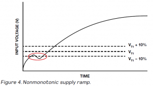
It is important to use a monotonic power supply, as a non-monotonic ramp could cause a problem if the deviation is close to any threshold level. The high threshold variation can cause the same non-monotonic sequence to work in one unit, but fail in others, as shown in Figure 4.
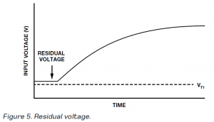
Sometimes, even when the supply is disconnected (low-dropout or LDO disabled), storage capacitors retain some residual voltage, as shown in Figure 5. This voltage should be kept as small as possible to guarantee that the supply drops below VT1 or the POR will not reset correctly and the device will not initialise correctly.
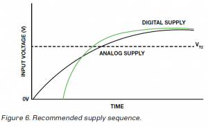
Some data sheets define the recommended supply sequence that should be applied to devices that have more than one supply pin. It is important that this sequence be followed. For example, consider a device with two independent supplies. The recommended supply sequence states that the digital supply must be powered before the analogue supply (this is common; as the digital block controls the analogue block it must be powered first). The sequence states that the block must be initialised first. It does not matter which supply starts to ramp first, but the digital supply must cross the threshold before the analogue supply, as shown in Figure 6. If the delay between supplies is on the order of 100µs, the impact should be minor and the device should initialise correctly.
Due to internal transistor parasitic, slow supply ramps on the order of 100ms can cause problems. The POR circuit is evaluated at various slew rates to guarantee correct operation within normal power conditions. The data sheet will state whether a fast supply ramp (100µs or less) is required.
A poor ground connection, for example, from a board connected to the supply with a thin cable, will have high ground impedance, which could generate glitches during power-up. In addition, in some electromagnetic environments (EME), the parasitic gate capacitance of the metal-oxide semiconductor (MOS) transistor can charge, causing it to malfunction until the capacitance is discharged. This could cause a failure in the POR initialisation.
Drift and tolerance need to be considered as well. In some cases, discrete components such as capacitors have high tolerances—up to 40 per cent—and high drift versus temperature, voltage and time. In addition, the threshold voltages have a negative temperature coefficient. For example, VT1 could vary from 0.8V at room temperature to 0.9V at –40°C and 0.7V at +105°C.
Importance of voltage accuracy and transitional behaviour
Now you know some common issues that could cause system problems when powering a board, and the basic rules to guarantee correct board initialisation. The supply is often overlooked, but both its final voltage accuracy and its transitional behaviour are important.
Click here to read about the difference between power-off and power-down modes of an IC.
Reference
Insight into digiPOT Specifications and Architecture Enhances AC Performance – Analog Dialogue, Volume 45, Number 3.
The author is an applications engineer in the Linear and Precision Technology Group at Analog Devices Inc in Valencia, Spain.
