 The idea of cell-based mobile radio systems originated at Bell Laboratories, USA, in the early 1970s. However, mobile cellular systems were not introduced for commercial use until the 1980s. During the early 1980s, analogue cellular telephone systems experienced a very rapid growth in Europe, particularly in Scandinavia and the UK, France and Germany. Today, cellular systems are still one of the fastest-growing telecommunication systems.
The global system for mobile communications (GSM) is a digital cellular communications system. In the beginning of cellular systems development, each country had its own system, which was an undesirable situation. In order to overcome this, the Conference of European Posts and Telecommunications (CEPT) in 1982 formed the ‘Group Special Mobile’ (GSM) in order to develop a pan-European mobile cellular radio system (GSM later became the acronym for ‘global system for mobile communications’).

In 1989, the responsibility for GSM specificaions passed from CEPT to the European Telecommunications Standards Institute. GSM specifications describe the functionality and interface for each component of the system, and provide guidance on the system design. These specifications also standardise the system in order to guarantee proper working between different elements of the GSM system. In 1990, phase-I of GSM specifications were published but the commercial use of GSM did not start until mid-1991.
At present, GSM operates in 900MHz and 1800MHz bands in Europe, and 850MHz and 1900MHz bands in the US. Together with international roaming and support for a variety of services such as mobile telephony, data transfer, fax, short message service and supplementary services, GSM comes close to fulfilling the requirements for a personal communication system—close enough that it is being used as a basis for the next-generation mobile communications technology. GSM modules are modules based on GSM technology.
Architecture of the GSM network
Fig. 1 shows the architecture of the GSM network along with the network interfaces. The GSM network is made up of three sub-systems: mobile station (MS), base station sub-system (BSS) and network and switching sub-system (NSS) comprising a mobile switching centre (MSC) and associated registers. The interfaces define between each of these sub-systems include Um air interface between the MS and BSS, Abis interface between the base transceiver station (BTS) and base station controller (within BSS), and ‘A’ interface between the BSS and NSS.
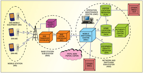
Mobile station. The MS comprises mobile equipment (ME) and a smart-card called the subscriber identity module (SIM) used by a subscriber to connect to the network. The ME is uniquely identified by International Mobile Equipment Identity (IMEI) number.
The SIM card stores permanent and temporary data about the mobile and the subscriber. The network contains International Mobile Subscriber Identity (IMSI) used to identify the subscriber to the system, a secret key (Ki) for authentication and algorithms for authentication checks. IMEI and IMSI are independent, thereby allowing personal mobility.
Base station sub-system. The BSS consists of one base station controller (BSC) and one or more base transceiver stations (BTS)—a network component along with a transceiver that serves one cell, provides radio access to the mobile stations and manages the radio access aspects of the system.
The BSC is a network component. It performs radio resource management for the cells under its control. It assigns and releases frequencies and timeslots for all the MS in its area. The BSC performs the inter-cell handover for the MS moving between the BTS in its control. It also reallocates frequencies to the BTS in its area to meet locally heavy demands during peak hours or special events. The BSC also controls the power transmitted by the BTS or MS.
Network and switching sub-system. The NSS combines the call routing switches (MSCs and gateway MSC) with database registers required to keep track of the subscribers’ movements and use of the system. The main role of the MSC is to manage the communications between GSM users and other telecommunication network users (Integrated Services Digital Network (ISDN), Public Switched Telephone Network (PSTN), Packet-Switched Public Data Network (PSPDN) and Circuit-Switched Public Data Network (CSPDN) users).
The MSC performs billing on calls for all the subscribers based in its ar-eas. When a subscriber is on roaming elsewhere, it obtains data for the call-billing from the visited MSC. The MSC specificall performs such functions as paging, resource allocation, location registration and encryption.
Associated registers. The home location register (HLR) contains all the administrative information of each subscriber registered in the corresponding GSM network, along with the current location of the mobile. There is logically one HLR per GSM network, though it may contain several physical HLRs depending on the number of mobile subscribers, capacity of the equipment and the organisation of the network. However, even if the HLR comprises geographically-separated hardware, it logically forms a single virtual database.
The visitor location register (VLR) is a database serving temporary subscribers within an MSC area. Each MSC in the network has an associated VLR that may serve many MSCs. A mobile station roaming in an MSC area is controlled by the VLR associated with that MSC.
When an MS enters a new location area, it starts a registration procedure. The MSC incharge of that area notices this registration and transfers the identity of the location area where the MS to the VLR is situated. If this MS is not yet registered, the VLR and HLR exchange information to allow proper handling of calls involving the MS.
The authentication centre (AuC) is associated with an HLR and stores an identity key for each mobile subscriber registered with the associated HLR. This key is used to generate data, which is used to authenticate the IMSI. The key is also used to encrypt user-data and cipher communication over the radio path between the mobile station and the network.
The equipment identity register (EIR) is a database that contains a list of all valid mobile equipment on the network, where each mobile station is identified by its IMEI number. The status returned in response to an IMEI query to the EIR may be white-listed, grey-listed or black-listed. The white-listed ME is allowed to connect to the network. Grey-listed means that the terminal is under observation from the network for possible problems. The black-listed terminal has either been reported stolen or is not type-approved (the correct type of terminal for a GSM network). Black-listed terminals are not allowed to connect to the network.
GSM security mechanisms
GSM standard was designed to be a secure mobile phone system with strong subscriber-authentication and over-the-air transmission encryption. The security model and algorithms were developed in secrecy and were never published. GSM system provides solutions to a few important aspects of security including:
1. Authorising network access (authentication)
2. Protecting user-identity confidentiality (use of temporary identities)
3. Protecting user-data confidentiality (use of encryption)
4. Protecting network signalling information and the SIM module, which plays an important role in GSM security
A personal identification number (PIN) code is used as a local security (network security is not involved here) for authentication of the SIM. The PIN is stored in the SIM and is asked when the mobile phone is switched on. If three faulty PIN inputs are entered, a longer personal unblocking key is asked. If ten faulty unblocking key inputs are keyed-in, the SIM gets locked.
Authentication. Since Um is vulnerable to fraudulent access, it is necessary to determine whether the IMSI received from the mobile subscriber is from the SIM that was assigned this particular IMSI. For this purpose, authentication of mobile subscribers is done. It is also done to protect the network against unauthorised access. It provides a degree of protection for GSM subscribers by preventing intruders from impersonating authorised users.
A request for authentication can be initiated by the MS or the network. The authentication process involves three items of information:
Ki key. A ciphering key stored permanently only in the MS SIM and in the subscriber profile in the AuC
RAND. A random number generated within the AuC
SRES. A ‘signed result’ code generated in the AuC by passing the Ki and RAND through A3 algorithm
Authentication is built around this notion and Ki that reside in only two places—in AuC and in the user’s SIM card. Since Ki is never transmitted, it is virtually impossible for unauthorised individuals to obtain this key to impersonate a mobile subscriber.
The AuC upon request from the MSC generates a number of security information ‘triplets’—each comprising a RAND, an SRES and a Kc key (the key is generated as part of the triplet but used for encryption rather than authentication). This group of triplets is sent to and stored in the VLR associated with the MS. Each time an authorisation is requested, a new triplet is used. If all triplets held in the VLR are used, the MSC requests a new batch from the HLR/AuC using a “Send Authentication Info” message. The HLR/AuC responds with this information using a “Send Authentication Info Ack” message.
The authentication process is shown in Fig. 2. The subscriber (MS) requests network access by sending its IMSI/temporary mobile subscriber identity (TMSI) to the MSC. The IMSI is sent to the MSC only in the case of first-time entry of the MS into the network or data loss at VLR. The MSC checks whether its VLR holds a valid unused triplet. If not, new pairs are requested from the AuC.
The AuC using the IMSI extracts the subscriber’s Ki. It then generates RAND and applies Ki and RAND to the authentication algorithm (A3) and cipher key-generation algorithm (A8) to produce an authentication SRES1 and a Kc. The AuC then returns an authentication triplet—RAND, SRES1 and Kc—to the VLR.
The MSC/VLR keeps the two parameters—Kc and SRES1—for later use and sends the RAND component of the pair to the MS using an “Authentication and Ciphering Request” message. The MS reads its Ki from the SIM and applies the received RAND and Ki to A3 and A8 to produce SRES2 and Kc. It saves Kc to be used when it receives the command to cipher the channel. The MS returns the generated SRES to the MSC/VLR using an “Authentication and Ciphering Response” message.
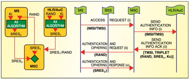
The MSC compares its self-generated SRES1 with that received from the MS. If these are identical (SRES1=SRES2), the user is authenticated and granted access to the network. If these are unidentical (SRES1≠SRES2), all signalling activities are aborted.
User-identity confidentiality.Subscriber identity confidentiality provides for the privacy of GSM subscribers’ identities by ensuring that the IMSI is not disclosed without authorisation. This prevents the intruder from tracing the location of mobile subscribers, gaining information on the resources in use, and matching the user and transmitted signal.
Protection of a subscriber’s IMSI is achieved by issuing a temporary replacement ID known as TMSI. This identity is allocated by the VLR when a subscriber firs affiiates to the network and may be subject to change each time the subscriber reconnects to the network or moves between MSCs (and hence VLRs).
User-data confidentiality (encryption). The confidentiality and privacy of user data on physical connections is achieved by user-data encryption. The encryption prevents the user-data disclosure to unauthorised individuals, entities or processes. GSM recommendations have indicated seven ciphering algorithms and given provision to select one or more algorithms for the mobile station and/or GSM network. The GSM network is responsible for deciding which algorithm to use.
When encryption is requested, the MS signals the network indicating which of the seven ciphering algorithms it supports. The serving network then selects one of these, and signals this to the MS. The selected algorithm is then used by the MS and network. Normally, a standard algorithm (A5) is employed. It is noteworthy that the GSM network has the fexibility not to use encryption in which case-confidentiality is not applied. Th general GSM encryption process is shown in Fig. 3.
Determining the algorithm. After the authentication process, the MS requests the network to establish an encrypted connection. Depending on the priorities, the A5 algorithm (or any other algorithm selected by the network) is first negotiated. The priorties are:
1. If the MS and the network have no common versions of the A5 algorithm and the network and/or the MS is not prepared to use an unencrypted connection, the connection is released.
2. If the MS and the network have at least one version of the A5 algorithm in common, the network selects one of the mutually acceptable versions for use on that connection.
3. If the MS and the network have no common versions of the A5 algorithm and the network is willing to use an unencrypted connection, an unencrypted connection is es-tablished.
Kc key generation. The Kc key is generated at both the MS and the AuC by applying the cipher key-generation algorithm (A8) to RAND (generated by the AuC) and Ki—unique to each MS. Kc key generated at the AuC is passed to the MSC/VLR along with RAND and SRES as part of each triplet.
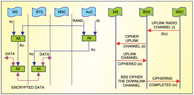
Ciphering. Encrypted data is produced by passing the Kc key, and the clear user-data through A5 algorithm is stored in the MS and BSS. The transition from clear mode to ciphered mode proceeds as follows:
1. The MSC/VLR requests the BSS to cipher the radio channel. Included in this message is Kc, which was made available earlier during the authentication process.
2. The BSS retrieves Kc from the message and transmits a clear “Start Cipher” message to the MS requesting it to start ciphering the uplink channel.
3. Once this message is received correctly, enciphering and deciphering start on the MS side.
4. Enciphering on the BSS side starts as soon as synchronisation is achieved and an encrypted MS-generated frame or a message is correctly deciphered at the BSS. The BSS upon ciphering the downlink channel sends a “Cipher Complete” message to the MSC.
Protection of signalling information. In order to ensure the confidetiality of user-related signalling data exchanged between the MS and BTS, the encryption of signalling data is done. Signalling information elements like IMSI, IMEI and calling/called sub-scriber directory number are protected whenever used after initial connection establishment.
The author is a junior telecom officer at Bharat Sanchar Nigam Ltd (BSNL) pursuing PhD in electronics engineering from Institute of Technology, Banaras Hindu University, Varanasi