


Read Part 1
Interconnection networks are high-speed computer networks. These are connections between nodes where each node can be a single processor or a group of processors or memory modules. These connections carry or transport data from one processor to another, or from the processor to the memory so that the task is broken down and computed in parallel.
Individual networks have their own coverage area. The need was felt to extend the coverage area of networks by inter-networking. In particular, the need was felt to achieve global connectivity to take full advantage of networking, namely, global linking, resource sharing and load sharing.

There were two challenges in inter-networking for global connectivity. Different countries have their own policies, programmes, priorities, choices and preferences. As such, it was impossible to use jurisdictional geography of one country by another to implement physical interconnecting networks.
Moreover, individual networks of different countries are designed based on different protocols. Protocol of a network is a set of rules for the functional operation and connection of nodes, devices and computers to the network. However, resolving the incompatibilities of individual networks for inter-networking was a challenge.
Gateways as devices are one set of tools for resolving the issue. Protocol converters are typical examples of the simplest gateways. For example, let us assume three individual networks, namely, a, b and c, are designed for three different protocols, namely, A, B and C, respectively. One resolution to fix the incompatibilities of communication between all devices connected in these networks, when interconnected, can be using several protocol converters, like A to B and B to A for communication between networks a and b; B to C and C to B for communication between networks b and c; and A to C and C to A for communication between networks a and c. Altogether, as many as six different protocol converters are needed.
So, what will happen when thousands of computer networks all over the world are connected? Cost-wise, it will be huge, and administrative jurisdiction over the converters will remain debatable.
The Internet, thereafter
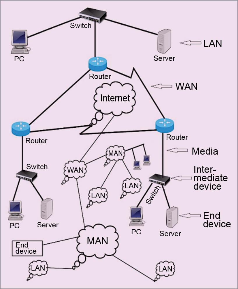
The Internet (Fig. 1) came as a solution for world-wide systems of interconnected computer networks to take care of the above-mentioned challenge of global connection. It does so by using a single global protocol known as Internet Protocol (IP) over either Transmission Control Protocol (TCP) or Universal Datalink Protocol (UDP).
TCP/IP as well as UDP/IP are known as protocol suites. The Internet is best defined as a global network to link globally-distributed computers to share, exchange and provide services of World Wide Web (WWW), e-mail, voice, video, messaging and multimedia services.
The Internet, or simply the net, may also be called a network of networks. It connects millions of local area networks (LANs), metropolitan area networks (MANs), wide area networks (WANs), academic, business and state networks, which are geographically distributed all over the globe.
The Internet is the world’s single backbone network that connects other networks and computers using an open system of architecture of TCP/IP or UDP/IP. For accessing the Internet, users are required to take the service of a local Internet service provider (ISP). An ISP acts as a middleman between users and the Internet.
The concept of the Internet originated in Advanced Research Projects Agency (ARPA) in the US. It was first implemented in December 1990 in CERN, Switzerland. Growth of the Internet is more than the growth rate of any other technology. A glimpse of its leaps and bounds growth is given below.
- 44 million Internet users in 1995
- 413 million Internet users in 2000
- 3.7 billion Internet users in 2016 (49.5 per cent of world population)
- 4.2 billion Internet users in 2017 (54.4 per cent of world population)
The first Asian to win a Nobel Prize is an Indian. He was Rabindra Nath Tagore, the great poet. His established far-reaching thinking was of a one world, one village. The great idea of a genius son of India is, in fact, on the verge of being achieved through the Internet.
TCP/IP and UDP/IP protocol suites
A protocol defines a set of rules for the functional operation of any computing system. As part of the process, a protocol resolves the problems of incompatibility and the overlaps existing in different systems. A protocol is also followed in offices. For example, a personal secretary follows a prescribed functional protocol to work with the boss. And, an attendant follows a different protocol so that there is no clash in running the office.
In 1984, International Standards’ Organization (ISO) of Europe developed an open systems interconnection (OSI) model for communication in networks. OSI is a layered reference framework of standards for communication among different parts of a network and/or among networks made of different equipment and applications by different vendors.
Incompatibilities are resolved by the application of reference model OSI. Over the years, OSI has been accepted as the basic and main architectural model for inter-computing, networking and internetworking communications. As of today, most networks are based on
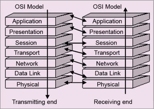
OSI model. Seven layers of OSI reference model divide communication into seven peer processes, which are independent to each other.
The independent nature of implementing functions in each layer makes the design flexible and modular. The function of a layer may be set without affecting the functions of the other layers. For implementing the function of each layer, a set of rules called protocol is defined.
In OSI model, within each layer, one or more entities implement their functionality. Each entity interacts directly only with the layer immediately below it on the transmission end and provides facilities for use by the layer above it. Conceptually, at each layer at the transmitting end, a header is added with payload; and at the receiving end, a header is removed, as illustrated in Fig. 2.
Functions of the seven layers of OSI model are:
- The physical layer defines the physical properties (for example, characteristics of signals and codes used for signals) of the various communication media used between a transmitter and a receiver. Physical properties include electrical properties, type of cable used, type of BNC connector used, termination method, signal coding and so on. Cables may be coaxial, Ethernet, twisted pair or other. The layer therefore takes a decision on the method of transmission of bits as physical signals. The logical bit pipe received from the data link layer is converted into physical signals at the transmitter end. Physical signals received by the receiver are converted back into a logical pipe at the receiver end. This makes layer-to-layer functionality a peer process.
- The datalink layer does the logical frame of data bits transmitted/received over the physical layer. At the transmitting end, the layer generates a logical bit pipe with several overheads like address of source and destination, error check sum, length identification and so on, and at the receiving end, the bit pipe is decomposed (by removing the overheads after due processing/checking as the case may be) into received data bits.
Several protocols are used for the organisation of data bits at this layer. Examples of the protocols are SDLC and HDLC. Data bits are put into a frame that includes headers of address (source and destination), control, check sum, and start and end of frame bytes.
LAN is functionally made up of datalink and physical layers. LAN being a shared media network, the datalink layer for LAN has two functions: logical link control (LLC) sub-function and media access control (MAC) sub-function.
- The network layer performs routing and switching. It describes how data packets/frames traverse over various data links in the network between the source and destination. The layer defines the addressing and routing of the Internet. A node is made of three layers: physical, datalink and network.
- The transport layer takes care of the quality and nature of data delivery. Quality of data delivery refers to issues like fast delivery versus normal delivery.
- The session layer manages how to handle packets to be transported by various networks, nodes and links. It establishes a logical session for transport.
- The presentation layer makes the data presentable (encryption/decryption, for example) for transport by syntax, technique for floating point numbers and so on.
- The application layer defines the type of application of data to be transported. It implements, for example, file system operations.
A protocol suite used in the Internet is for the standard networking of isolated networks of various types. It is made of more than one protocol. TCP/IP as well as UDP/IP are both protocol suites developed for the Internet.
TCP/IP is a four-layered protocol (Fig. 3), where layer 1 is the network interface service layer. It corresponds to layers 1 and 2 of OSI/ISO protocol. It provides services related to MAC, device drivers, physical medium, physical attachment and physical signals. In this layer, datagrams are packaged into frames.
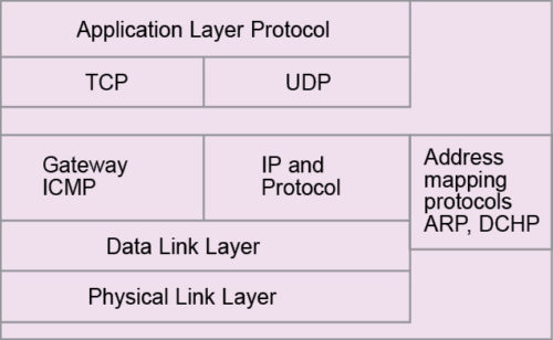
Layer 2 is the IP layer. This layer corresponds to layer 3 of OSI/ISO protocol. It provides the routing of datagrams as units of data. Logically, these are packets. The service is connectionless; hence, switching is a datagram service rather than virtual circuit switching.
IP provides the basic service of getting the datagram to its destination. IP receives TCP packets from the upper layer TCP and then it forms its own packet, known as IP packets. Each IP packet is associated with several IP headers. For example, an original data is fragmented into three packets at TCP layer as: data pack 1, 2 and 3. Each data pack is added with TCP headers to make TCP packets.
TCP Packet = Data Pack + TCP headers (added at TCP layer)
Now, TCP packet is sent to the IP layer. With each of the TCP packets, IP layer adds IP headers making an IP packet (frame or datagram).
IP Packet = TCP packet + IP headers (added by IP layer)
Then, IP datagram is released to the physical layer.
IP header descriptions
The current version of IP that is in use mostly is version 4, denoted as IPv4 (though IPv6 is also now in use in many places). Formation of packets under IPv4 is made with headers as shown in Fig. 4. Various headers are described as next. Headers at each level is made up of 4 bytes or 32 bits.
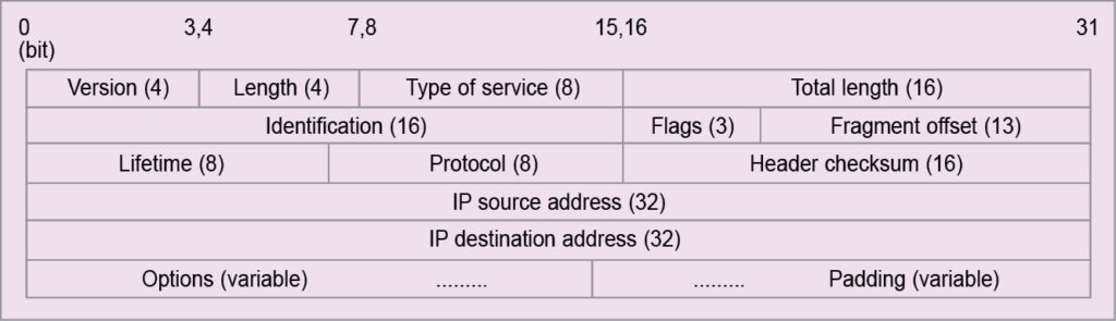
Headers at the first level are:
- 4-bit version field, which indicates IP version used in the IP datagram. The most widely-used version is IPv4. IPv6 (IP version 6) has already emerged as a better alternative.
- 4-bit length field, which is also known as the Internet header length (IHL). It contains information about the number of 32-bit words in the header of the IP datagram. The minimum number of headers in any IP datagram is five 32-bit or 20-byte words. This happens when there is no other option or padding field.
In this case, the IHL field contains 0101. As the IHL field can have the maximum value as 1111 (=15), maximum number of headers in any IP datagram is fifteen 32-bit or 60-byte words. As the number of headers are in multiples of 32-bit or 4-byte words, headers that an IP datagram can carry is one of the following sizes: 20, 24, 28, 32, 36, 40, 44, 48, 52, 56 or 60.
- 8-bit type of service (TOS) field, which indicates whether the IP datagram should receive any special type of service. Based on the indication about special service offers, priority or precedence is given to the particular packet(s) over other packet(s). This enables the routers to choose the appropriate path for the transport of the packet(s).
In the past, this field was largely unused. TOS field splits into two sub-fields: 5-bit D/T/R/C/R (low delay/high throughput/high reliability/low cost/reserved) and 3-bit precedence.
Precedence is absolute and not relative. An IP datagram for a regular packet with no special priority will have D/T/R/C/ sub-field set as 0000 and precedence sub-field set as 000. Consider a multimedia packet that may need a higher throughput and highest-level precedence. For a multimedia packet like that, IP datagram will set D/T/C/R sub-field as 0100 and precedence sub-field as 111.
TOS field is used by routers to choose the routing path. If a regular datagram that needs a normal service reaches a router, the router selects a normal route as per the outing strategy. But when a datagram requiring minimum cost reaches a router, the latter selects a path with minimum number of hops.
Similarly, for a datagram with higher reliability, the router selects a more reliable (lower BER) path. Likewise, for a datagram with higher throughput, a path with higher link capacity needs to be selected. The standard is already set for various services of different TOS fields.
- 16-bit total length (TL) field, which indicates the total number of bytes that the datagram carries including headers. Maximum number of bytes that a datagram carries, when all 16 bits are 1s, is 65,535. IHL field counts only the header fields in units of 32-bit or 4-byte words. But TL counts the entire packets in bytes.
The entire IP datagram is variable and so are header fields. Using IHL the receiver identifies the number of header bytes in a packet. The receiver, by subtracting header bytes from total bytes, identifies the beginning and end of data, which is the TCP pack.
At the second level, there are three headers, as follows:
- In the identification field, a 16-bit header connects the different types of networks designed to carry packets of different sizes. For example, Ethernet packets may be in the rage of 64 to 1518 bytes, MAN may have a maximum packet size of 1500 bytes, FDDI packet can be of 4472 bytes and a token ring packet may be typically of 17,800 bytes.
When a packet of, say, 1500 bytes arrives at a node or router, and the same is required to be transferred or routed to a network, say, having maximum packet size of 512 bytes, it is required that the arriving packet of 1500 bytes is fragmented into several smaller packets, each having a size of 512 bytes or less.
Each part or fragmented packet of a particular original packet must be given some identification so that the receiver can recombine all related fragments in packets. Same identification to all fragments of a packet ensures that wrong fragments are not combined to reconstruct the original packet in the receiver. The identification field assigns a single group number to all fragments of a packet being fragmented.
- 3-bit flags are used to control and convey information with regards to fragmentation. The left-most bit is reserved. The middle bit known as don’t fragment (DF) provides flexibility to the sender. If the sender wishes that the packet must not be fragmented, even if it does not reach the destination, he or she can construct an IP datagram with DF bit set to 1.
When DF bit is set to zero, fragmentation is allowed. When a node or router breaks a packet into several fragments, more fragment (MF) bit of all fragments, except the last one, is set to 1. MF bit is set to 0 in the last fragment. By this, the receiver is made aware about the last fragment of a packet.
- 13-bit fragment offset indicates how to insert fragments in the receiver’s buffer to reconstruct the original datagram. The field is measured in units of 8 bytes. This is because there are only 213 offset values but the datagram can be as big as 216 bytes. So each fragment must be in multiples of 8 bytes, as 213/216=8.
This requirement applies only to the data field (or TCP pack) of the original packet, because header fields of the original IP by right are also the header fields of each fragment. One cannot expect the header fields to be always divisible by 8. So a fragment’s data field will always be in multiples of 8 bytes, but total length of the fragment (total length of fragment = original packet header length + data length of fragment) will be in multiples of 4 bytes.
However, total length of the fragment may be made in multiples of 8 bytes by padding for the purpose of storing at the receiver. Multiples of 8 bytes are only applicable to data fields, not to the whole datagram. In the worst case, data fields may be just 8 bytes. So for permissible header lengths, the worst-case fragmented packet sizes would be 28, 32, 36, 40, 44, 48, 52, 56, 60, 64 and 68 bytes.
But IP does not run over the networks that have the maximum transmission unit (MTU) smaller than 68 bytes—this is the highest fragment size as a worst-case scenario. Thus, for an IP datagram of 20 bytes IHL, the worst case refers to fragments having data field in multiples of 48 (68-20) bytes.
Since, 48 bytes are multiples of 8 bytes, consider an original IP packet with 20 bytes minimum IHL and 65515 (65535-20) bytes maximum TL. In the worst case, an original IP packet may be fragmented into 1364 (65515/48) fragments with remaining 43 bytes left over as the 1365th fragment, which is made 68 bytes long by padding.
Headers at the third level are:
- 8-bit lifetime or time-to-live (TTL) field that is used to ensure that an IP packet does not persist in the Internet forever. If the packet persists in the network forever, congestion is bound to occur. So TTL, in its own right, provides a mechanism to avoid congestion in the Internet. Maximum TTL field is 255. In the early days, it was taken as 255 seconds.
Presently, TTL field is taken as a hop counter. Thus, an IP packet can move maximum 255 hops in the Internet.
The transmitting station sets the TTL field of the datagram. When the datagram passes through routers or nodes, each router or node decreases the TTL field by the default value set by the router or network administrator; minimum value of default being 1. If a router or node receives a datagram with TTL field as 0, and if the datagram does not reach its final destination, the datagram is discarded by that router or node.
- 8-bit protocol field that defines the protocol in which data is encapsulated. For example, when the IP datagram carries a protocol field with 6, it means data is a TCP pack. The standard is already set and available for various encapsulating protocols. For UDP it is 17.
- Header check sum field that is of 16 bits. This field is used to check errors on the header fields of the IP datagram. Checksum is calculated using 1s complement addition rule, which was discussed earlier. It is computed by taking 16-bit words from header fields. The checksum field ensures checking of errors only at link level on header fields.
TCP performs end-to-end error control, which takes care of errors on the data field. That is why at IP level, error checking at the data field is not done. IP header checksum is computed at each router or node, or on hop-to-hop basis, since each router/node changes the TTL field as well during fragmentation of IP headers (like identification, M flag, offset fields, etc).
The next two levels are for addresses. IP header has two address fields: source IP address and destination IP address. These are used to route datagrams. Similarly, addresses are used in postal letters. IP uses four modes of addressing for this purpose. These are known as A-class, B-class, C-class and D-class. The difference in classes is due to the number of bits used for network identification and the number of bits used for host identification.
Different address formats under different classes are illustrated in Fig. 5. IP addresses are of 4 bytes, and these are usually mentioned as four sets of dot-separated octets. For A-class, most significant bit of the first octet is always 0. Therefore the next seven bits are used for network identification. This means that only 27 to 128 networks can be of A-class. Hosts may be 224.
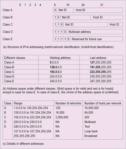
For B-class address, first two bits of the first octet must be 10. This means the first octet has to be from 128 to 191. 127 is reserved for special purposes. Total networks and hosts under this class are, respectively, 214 and 216.
For C-class address, first three bits of the first octet are 110. This means the first octet will be from 192 to 255. Class-C address has 221 networks and 28 hosts. Minimum hosts under different addressing modes are:
Class A: 27×224=231
Class B: 214×216=230
Class C: 221×28=229
Address scheme under A-class to C-class is for unicast (one-to-one) communication. Other addressing schemes are for multicast (one-to-many) communication. Class-D and Class-E belong to multicasting.
In D-class, all four octets are used to identify the group of nodes designated to receive a multicast. D-class addresses do not specify the network. These are in the range of 224.0.0.0 to 239.255.255.
E-class addresses range from 240 to 255 in the first octet, and are used for experimentation.
Maximum number of hosts or nodes per network are in A-class, and it is about 28 times that of B-class and about 216 times that of C-class. Maximum number of hosts or nodes per network in B-class is about 28 times that of C-class. The logical conclusion is that A-class addressing is for larger networks, B-class for medium and C-class for small networks. So, if your network is large, you can apply for A-class address, for medium network, B-class and for small network, C-class address.
An organisation may opt for any one of these classes based on size. Say, an organisation has 2000 hosts under its local network. Thus, it cannot opt for C-class address, because under one network address of C-class, maximum 128 hosts can be addressed. The optimal option is then for B-class, because under a network address of B-class, maximum of 216 hosts can be addressed.
Special addressing schemes are as following:
- Address 0.0.0.0 means that this host is on the network. It actually refers to the Internet itself.
- 255.255.255.255 is used as a broadcast (one-to-all communication) packet for all networks. A network ID with host IDs with all 1s or 255 is used for directed broadcast to the network. For example, 20.255.255.255 is used for a broadcast message to A-class network with ID 20. Broadcast addresses are destination addresses.
- Packets with first octet as 127 are used for network testing. An address with network ID as 127 and host ID of any address is used for internal host loop back address. Thus, loop-back addresses are 127.0.0.0 to 127.254.254.254
- An entire network is specified by providing only the network identification and with 0s in all other octets, such as 125.0.0.0 for A-class network, 129.150.0.0 for B-class network and 208.127.110 for C-class network.
- A specific host on the network is specified by network ID as 0s and with required host ID. This is used as a source address.
At the last level, two headers are option and padding. Option field in the IP header is optional. This field is made of option-type field, followed by option length field and then option data bytes. Option type is the first byte of option header, and it has three fields: 1-bit copied flag, 2-bit class field and 5-bit number field.
When copied flag bit is 0, option field is not copied in the fragments of the IP datagram. But when it is set to 1, option field is copied in all fragments of the IP datagram. The different option classes are as under:
00 for Control
01 for Reserved
10 for Debugging
11 for Reserved
where the numbers are used as:
0 for end of option list followed by 0 bytes
1 for no operation followed by 0 byte
2 for security followed by 10 bytes
3 for loose source and record routing (LSRR) followed by variable bytes (allowable maximum length is of 255 bytes in total)
4 for Internet timestamp followed by variable bytes, maximum of 255 bytes in total
7 record route (RR) followed by variable bytes, maximum of 255 bytes in total
8 for stream identification followed by 3 bytes
9 for strict source and record routing (SSRR) followed by variable bytes, maximum of 255 bytes in total
End-of-option list has type 0 as its option type; byte has a value of 0 (00000000). It belongs to class 00. This option field is used as the end of all options but not the end of each option. However, it does not necessarily coincide with the end of all IP headers as per the IP header length field. This is because padding is needed to make IP headers a multiple of 32 bits words. End-of-option field may be copied, introduced or deleted on fragmentation.
No operation option field is used between options for the purpose of alignment for 32-bit words. This field has a type that is equals to 1 (00000001) and belongs to control class 00. It may also be copied, introduced or deleted on fragmentation.
Security option field belongs to control class. The field has type 130 as its option type field and carries a value of 130 (10000010). The length field carries a value of 11 (00001011), as it has total 11 bytes.
Other option fields are SSS…SSS, CCC…CCC, HHH…HHH and TCC…TCC.
SSS is a 2-bytes security field that specifies different levels of security. Examples are 00000000 00000000 for unclassified with code as 00110101 11100010 (reserved), 11110001 00110101 for confidential with code as 01001101 01111000 (reserved), 10101111 00010011 for restricted with code as 00010011 01011110 (reserved), 01101011 11000101 for top secret with code as 11000100 11010110 (reserved) and so on.
CCC field is also a 2-byte field. It is called compartment field. The field contains all 0s when data is not compartmented. Other codes are with Defence Intelligence Agency.
HHH is a 2-byte field known as handling restrictions field. Code of the field is available from Defence Agency.
TCC field is known as transmission control code, and is 3-byte long. It is used to segregate data and define control. It is also Defence Agency-controlled. The field must be copied on fragmentation.
Loose source and record routing (LSRR) is the options field that allows source of an IP datagram to define routing information to be used by routers/gateways to forward the datagram to its destination. This is also used to record the routing information. Thus, the options field provides alternative routes. Routing is specified by recording the IP addresses of routers and gateways in the data area of the options field. Routers and gateways may use the information provided in the route data to route the datagram, and may not use their own routing tables for the same.
The Internet time stamp options field has headers like copied flag as 0, debugging class (10) with number 4 (00100). The option field is therefore type 68, as type header has a value of 68 (01000100). One byte of length header specifies the number of bytes in the options field, with a maximum value of 40. The 1-byte pointer header indicates the byte at which the time stamp is to be recorded. Minimum value of the pointer is 5, as the first time stamp record must start 5 bytes after the pointer (1 byte for overflow + flags, 4 bytes for Internet address).
The 4-bit overflow header is used to hold the number of IP addresses (may be routers, intermediate nodes, gateways, etc) that cannot record the timestamp for want of space. The 4-bit lags are used to define different modes of recording time stamps. The time stamp is of 4 bytes or 32-bit words that record value for the number of milliseconds since midnight under universal time frame. If non-standard time record is made, any time can be recorded, but in that case highest order bit of the time tamp is set to 1. The Internet address refers to the IP address of the source that started the option.
The article is dedicated to Bob Metcalfe, who developed the Ethernet in 1973.
Read Part 3
Prof. Chandan Tilak Bhunia is PhD in computer engineering from Jadavpur University. He is also fellow of Institution of Electronics and Telecommunication Engineers, fellow of Institution of Engineers (India) and fellow of Computer Society of India.