


Read Part 2
Transmission Control Protocol (TCP) is the standard that defines how to establish and maintain a network conversation via which application programs can exchange data. TCP works with Internet Protocol (IP), which defines how computers send packets of data to each other. Together, TCP and IP are the basic rules that define the Internet.
The transmission control protocol (TCP) layer, or layer 3, corresponds to layer 4 of Open Systems Interconnection, developed by International Standards Organization (popularly known as OSI/ISO protocol). This is the transport protocol. The layer operates in connection-oriented mode and guarantees delivery of data. TCP provides the service of breaking messages into datagrams at the source end, retransmitting any datagram that has been lost or acknowledged negatively, sequencing the datagrams and so on.
Service in the layer is guaranteed by the acknowledgement of receipt of data from the receiving side. If acknowledgement is negative, data is retransmitted, and if it is not received within a time period, known as time-out period, retransmission of the packet is done. This layer also performs multiplexing and demultiplexing functions, if required.
The TCP layer makes TCP packs using the data received from application or higher layers. A TCP pack has many header fields, as shown in Fig. 1.
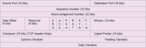
TCP headers
Like IP, a TCP header is minimum 20 bytes in length. It has the following fields:
- A 16-bit source port number, which refers to a virtual circuit between two end-stations of communicating parties. The port is also called a socket or session. In a port or socket, more than one process can communicate over a session at any time between end-stations or communicating nodes. The established link is shared and not dedicated.
- A 16-bit destination port, which refers to the port of the receiving device of an application process. TCP ports are defined in standard. Some of these ports are nine for transmission discard, 15 for status of network, 20 for file transfer protocol (FTP) data, 25 for SMTP e-mail applications, 80 for hyper text transfer protocol (HTTP) and 2049 for network file system (NFS).
- A 32-bit sequence number (0 to 4,294,967,295) field, which is used to assign a sequence number to each TCP pack. It is assigned to the first byte of the TCP message. The transmitter assigns the sequence number. The receiver, on reading the sequence number of the packs, ensures that all packs are received. Using a sequence number, packs received out of order are also placed in order. Using the sequence number, the receiver identifies duplicates of the packs, if any, and takes corrective measures, accordingly.
- IP sends datagrams that may be independently routed through deferent links. These, in turn, may deliver datagrams out of sequence at the receiver. Datagrams are put in order using sequence numbers assigned to these during transmission. This is done at the TCP layer. Sequence and acknowledgement numbers together ensure reliable transport of TCP, which is a reliable transport protocol, whereas IP is not.
- A 32-bit acknowledgement field, which is used to send acknowledgement of the pack received correctly. The receiver performs this function. It checks the sequence number of a received pack. If the pack is received without error, the receiver sends an acknowledgement number using the sequence number of the pack to inform the sender that the pack has been received correctly.
- A 4-bit offset field, which is used to indicate the number of header fields in units of 32-bit words. Offset field is also known as header length, or HLEN. If there are no padding and option fields in the header, offset field will be 0101. This means, there are five 32-bit words, or 5 x 4 = 20 bytes header. Using this information, the receiver determines the start of the data field so that data can be derived from the received pack.
Flags, window and urgent pointers are used to connect and manage the TCP connection. SYN (synchronisation), ACK (acknowledgement) and FIN (finish) flags are one-bit each. These are used to establish a TCP connection. TCP is a reliable and connection-oriented protocol. A TCP session needs a virtual connection, which is established by a process called TCP handshake. To establish a connection, the sender sends a TCP pack with SYN flag set to 1 and ACK flag set to 0. The calling program sends a TCP message through a port that has been allocated to it, like 21 for FTP connection. Initial connection requesting the TCP pack chooses a random number as the sequence number.
The connection-requesting message is a one-byte message. Thus, the random number provides the number to the calling sequence. This sequence number is called ISS (initial send sequence) for the receiver. If the random number is 250, this value is assigned to the calling sequence. If, and when, the receiver receives this pack correctly, it responds by sending a pack to the sender with both SYN and ACK flags set as 1 (SYN=1 and ACK=1).
The receiver chooses a sequence number by its random generator and sends a response message with this sequence number. If the chosen number is 350 (IRS, or initial receive sequence, number for the sender), the reply message will contain 350 in the sequence number field. The acknowledge number field contains the value 251 (meaning, the receiver is awaiting a message with sequence number 251 as it has already received message with sequence number of 250).
Once the sender receives the correct pack from the receiver, the former can send another pack with ACK flag set to 1 (that is, ACK=1), with sequence number field set to 251 and acknowledge number field set to 351. The connection is then established.
After the connection is established, communicating parties can perform transmission in full-duplex mode. Connection can be terminated by any station, either sender or receiver, by sending a pack with FIN flag set (that is, FIN=1). For example, after transmitting all data, the sender can send a pack with FIN flag set to 1. When this pack is acknowledged by the receiver, connection is terminated.
During connection request phase, the initial sequence number should be so chosen that previous connections (sockets) are not confused with new connection requests (sockets). This typically happens when a host application crashes and, before the other side times out, re-establishes the crashed connection quickly by recognising that the connection request is for the old socket.
ISN selection is made by a 32-bit random generator and is created during connection request phase. The number is generated by a 32-bit clock, which has ISN cycle of 4.55 hours. The clock is incremented approximately every 4µs, for which a unique ISN is generated with a cycle period of 4.55 hours.
- A 16-bit window flag, which indicates the number of bytes that the sender can transmit without receiving acknowledgements from the receiver. This field is used by the receiver to inform the sender about the availability of the buffer in the receiver. Based on this information, the sender controls the flow. Flow control is implemented by the window field.
- The urgent pointer field, which is used to alert the receiver about incoming urgent data and indicates the end of the urgent data within the sequence of the transmission of packs. Value in the urgent pointer is valid, provided URG (urgent) flag is set (that is, URG=1). Urgent pointer value defines the end of urgent data and the start of normal data in bytes. For example, if urgent pointer is 0000000001000000, the receiver will understand that the next 64 bytes of data will be urgent.
- Reserved bits (six bits) are for future use. All flags—URG, ACK, SYN, FIN, RST and PSH—together are known as control fields of TCP. PSH flag is set when the receiver is told to pass the data immediately to the application. Otherwise, the receiver will buffer the segments until sufficient storage is made. RST flag is used to abort TCP connection. When this flag is set, the receiver is advised to terminate the connection for an abnormal condition.
The options header can be of maximum 40 bytes and is always a multiple of four bytes. To make it, a multiple of four bytes padding may be used, if required. A few important options of TCP pack are:
Maximum segment size (MSS) option
This is used to indicate the maximum size of the segment that the sender can accept. This option is used during connection establishment phase. The sender specifies the MSS. This is a 16-bit option field. The largest block that MSS can specify is 216-1 = 65,535 bytes. A TCP pack or segment has minimum 20-byte header like that of an IP header. Thus, the largest block size of data that a TCP segment or IP datagram can carry is of 65,535 – 40 bytes=65,495 bytes. Declaration of MSS during connection setup is made to overrule TCP default MSS. TCP default MSS is 536 bytes.
Window scale option (WSO)
The TCP pack has a header of 16-bit window. Maximum permissible advertised window size is 216-1=65,535 bytes. With WSO, the larger advertised window size may be used for which upward scaling up to 214 is permissible. With WSO, scaled advertised window size may, hence, go up to 214×216-1 = 1.073,725,440 bytes.
Times stamp option
This is used for calculating round trip delay, which is used for calculating time-out period useful for flow control.
TCP divides data into manageable packets that are easier to deal with. It provides a guaranteed error-free connection. TCP breaks a network terminal (NT) service pack into several packets. If an error occurs, a small packet can be retransmitted instead of the whole pack.
TCP uses a header to establish a virtual connection to ensure successful transmission of packets and completion of transmission of the whole message. Source and destination port fields keep the trace of packets. Packets belonging to various applications, such as e-mails, on-line charts and multiple running browsers, can run concurrently based on the trace of packets. Sharing of an established virtual link is allowed at the same time. Sequence number is used to reassemble the packets at the receiver possibly received out of sequence due to sharing.
The receiver, on receiving a packet, performs check-sum operation to detect errors. If the packet is received error-free, a positive acknowledgement is sent. If packet is received erroneously, a negative acknowledgement is sent.
The transmitter, on getting either a negative acknowledgement within a time known as time-out period (TOP) or not getting any response within TOP, retransmits the earlier packet. This is Automatic Repeat Request Protocol (ARQ) for error control.
Flags, window and urgent fields are used to manage the TCP connection. Flags are used to connect and terminate a connection. Window field tells the transmitter the speed at which to send packets. When receiver buffer is full, the window is set to zero. This is how throughput is regulated by the transmitter sent by the receiver. Urgent field is used to send urgent information. When a receiver gets a packet with urgent field, it processes the packet with priority and acts accordingly, such as aborting transmission.
There are two variations of layer 3: user datagram protocol (UDP) and Internet control message protocol (ICMP). UDP is used when no sequence number is used. A simple example of this situation would be when a message can be put into one datagram. ICMP is simpler than UDP. Here, the message is put into one datagram only. Besides, the message is for the network and, hence, no addressing is required. ICMP is intended for TCP/IP software only.
UDP datagram is used to carry time-sensitive data like voice and video. UDP works in connection-less mode. It has fewer overhead bits, and overhead fields are quite simple. Format of UDP pack is shown in Fig. 2.
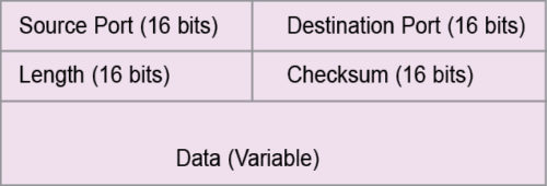
UDP headers
The 16-bit source port field indicates the address of the process at the sender, whereas process means the individual process that is in communication with the same process at the receiver.
The 16-bit destination port refers to the address of the port at the receiver that is in communication with the same process at the sender.
The 16-bit length field refers to the length of the whole UDP pack in bytes. Here, header fields are fixed, unlike in TCP. Data field is then determined from length field minus header field.
The 16-bit checksum field is used to check errors in the frame. Checksum measure is taken over the entire frame. When the receiver gets UDP frame, if calculated checksum is different from that of the transmitter, the receiver will detect the error.
A few commonly-used ports for UDP applications are 53 for DNS (domain name server), 123 for NTP (network time protocol), 161 for SNMP (simple network management protocol) and 2049 for NFS (network file system).
Above TCP/IP or UDP/IP suite is the application/higher layer. It may be layer 4 if the suite is taken as one single layer, or layer 5 if the suite is taken as two separate layers. From the Internet point of view, the suite is of single layer. Thus, layer 4 is the application layer, and this corresponds to the remaining higher layers of OSI/ISO protocol. Services of the layer include file transfer protocol (FTP), remote login, computer mail and program-to-program communication using socket programming interface and remote procedure call (RPC).
FTP allows a user, computer or terminal to get (or send) files to and from another computer. It is a tool of the Internet. Remote login is based on TELNET (network terminal protocol), which is another tool of the Internet. It allows any user to log into any computer in the network. Computer mail allows a user to send mails to another computer in the network—one classic example of this is e-mail. Each of the layers, while performing their functions, adds a header to the message/datagram at transmitting side—these headers are removed by the corresponding layer at receiving side. Layer-to-layer function is a peer process.
TCP/IP is an internetworking protocol. The Internet is an interconnected network of wide varieties of networks. Interconnection among different networks (often incompatible) is done by several methods, as given below.
- By repeaters that cover only the physical layer. An example would be an Ethernet to Ethernet connection.
- By bridges that cover physical and data link layers, corresponding to OSI/ISO protocol. An example would be connecting Ethernet LAN to token bus LAN.
- By routers that cover physical, data link and network layers (complete node coverage/node in OSI/ISO reference, which equals physical + data link + network layer). An example would be any IEEE802 series LAN to any X.25 WAN or MAN connection.
- By gateways that are used for connection networks of different protocols. A gateway covers all layers of a protocol. These are logically full protocol converters. An example would be a connection between an OSI/ISO network and a DNA network.
Repeaters, bridges and routers are used when interconnecting networks are of the same protocol. Gateways, repeaters, bridges and routers are all made of computing resources. In fact, these are all computers. Complexity of systems increases as one moves from repeaters to gateways. Bridges and routers can be defined as simple gateways. All these devices interconnect incompatible networks physically. The Internet does so logically for all networks globally.
Other Internet protocols
Address resolution protocol (ARP)
IP addresses are unique logical addresses, each assigned to a physical machine, system or node. An IP layer releases IP packets with IP logical addresses to the physical layer for the purpose of transport. The physical layer treats each IP packet as a data pack and encapsulates the pack into the physically-enabled transport packet commensurate to the physical network. For example, if the physical transport network is Ethernet LAN, IP packet as a data pack is encapsulated in the Ethernet frame. In making of the Ethernet frame, destination address required in the frame must be the physical address of the destination node.
Physical address is the address provided by network interface card (NIC) of the node. This is the only address that the physical transport network can recognise for transporting the Ethernet frame to the desired destination. Hence, before making the Ethernet frame, physical destination address must be known.
Software in a node determines the next node or hop based on the IP addresses in the IP packet. To transfer the IP packet to next node or hop, the corresponding physical address should be known. The address resolution protocol does the function of obtaining the physical address for a given IP address. It is like a telephone number, say, 03324315145, to know about the physical locations, which in this case are Kolkata (033), Tollygaunge (243) and subscriber location (15145).
Primitive technique used by ARP is table look-up technique, in which a table known as ARP table or binding table is used for address resolution. The table contains an array of data, each array having a protocol address and corresponding physical (=hardware) address. It is exactly like a telephone directory that contains tables of telephone numbers and corresponding physical persons’ names. For each separate physical network, separate ARP table or binding table is constructed. IP address entries in the table bear the same network ID for all nodes. As separate ARP table is required for separate physical networks, network ID (prefix of IP address)—being the same for all nodes—is omitted from ARP table to save memory space, like the telephone directory of Kolkata may not require code 033 in the table of directory.
Main advantage of table look-up is simplicity in operation. Once an IP address is known, a search of the table will resolve the physical hardware address of the corresponding node, host or computer. When a network has less than a dozen hosts or nodes, a sequential search will suffice. For networks having a higher number of hosts, nodes or computers, hashing or direct index search would be a better approach. Table look-up technique is basically used in WAN.
Closed-form computation technique of address resolution is another technique used in ARP. It is meant for networks that use the technologies of configurable addressing. In configurable addressing, physical addresses are not static. In closed-form computation, a computational, mathematical or relational function exists between the IP address and the corresponding hardware address. For example, a class B network with address 156.57.00001100.00000001 (host ID is underlined for illustration) is a configurable network. As and when computers are added to this network, physical addresses to the computers may be assigned such that 1s complement of the host’s ID in IP address becomes the corresponding physical address. Thus, the physical address, in the stated example, will be 00000000.00000001 (the 1s complement of host ID: 1111110011.1111110). Thus, a mathematical rule is for resolving address.
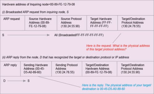
The message passing technique of address resolution is mostly used for address resolution in LAN. Nodes in LAN may work with look-up tables, too. In that case, look-up tables are known as ARP cache. To resolve any address, nodes first search their respective ARP cache. When ARP cache fails to supply the necessary resolution, message passing is evoked. The node then sends a broadcasted ARP request to all other stations of its network to find the link address of the target or destination IP address. Any station that recognises the target IP address sends a reply to the inquiring node. The reply contains the physical address of the target IP address. This technique is illustrated in Fig. 3. Source node S sends ARP request and node D sends ARP reply.
Reverse address resolution protocol (RARP)
Given a logical IP, the protocol used to derive its physical address is what is called ARP. Whereas, given a physical address, the protocol used to derive its logical address is RARP. RARP is the reverse of ARP. RARP is not so commonly used as ARP because most stations or computers know their IP address. All of these have a hard disk to store the same.
RARP is required for stations having no hard disk-like terminals or disk-less workstations. To run RARP, a RARP server is required in the network. A RARP server maintains a mapping table like that of a look-up table used in ARP. In ARP, all nodes are at par. But in RARP, the service is client-server oriented.
The inquiring node sends a broadcast RARP request. RARP server recognises the request and searches its database to find the protocol address for the given physical address of the inquiring node. The server then sends a RARP reply to the inquiring node. When a node sends RARP request, the destination hardware address will be the hardware address of the RARP server. The destination protocol address will be a broadcast address, which is net ID plus all 1s in the field of host ID. The message format will be that of the servicing node, both for ARP and RARP. If the service network is Ethernet, the message format will be of Ethernet frame.
The article is dedicated to Robert E Kahan and Vint Cerf, who developed protocol suite TCP/IP in 1978.
Read Part 4
Prof. Chandan Tilak Bhunia is PhD in computer engineering from Jadavpur University. He is also fellow of Institution of Electronics and Telecommunication Engineers, fellow of Institution of Engineers (India) and fellow of Computer Society of India.