Power management ICs (PMICs) implement critical functions in today’s complicated, sophisticated, multi-rail systems. While earlier-generation PMICs were limited to roles such as monitoring voltage rails to ensure they were within nominal tolerance range and protecting against under- and overvoltage conditions and faults, today’s PMICs offer many more features and functions, including the following.[1]
- System protection: Thermal management, undervoltage and overvoltage protection, and current monitoring to protect the device
- Power sequencing: Controlling the order in which sub-circuit rails in a system are powered up to avoid damage; eliminating the undesirable effects of power-up glitches
- Protecting systems from imminent power failure: Sensing and warning of primary rail issues before they result in loss of power at the output of a regulator
- Other features: Watchdog timer, manual reset, and battery-backup switchover
There are also less common application-specific PMICs that include additional functions, including:
- Voltage conversion and regulation: Integration of step-down (buck) or step-up (boost) regulators for converting a primary DC rail to the needed rail voltage
- Battery management: Manages charging/discharging cycles for batteries, including monitoring and safety features
The basic role of PMIC supervision is straightforward: to monitor the basic DC voltage outputs from DC/DC regulators and ensure they are within a defined window. If that output is too low, circuit ICs will perform erratically, and some functions and ICs will be turned on while others will be off or only partially on. The PMIC prevents the rail voltage from reaching the load by locking it out—a function called undervoltage lockout (UVLO). Conversely, if the rail voltage is too high, loads and ICs may be damaged. In this case, the PMIC implements overvoltage protection (OVP) to prevent excessive voltage from reaching the circuit.[2]
In general, power-subsystem designers want that subsystem to work as intended immediately on power-up. Any desired changes, such as adjusting the output voltage of a voltage regulator module via PMBus, are made to an already running and stable module.
However, while some PMIC functions, such as timing and delay, may be programmable, they are generally hardwired and not software-programmable. The reason is that requiring properly executing software to set up the PMIC is tricky: If the PMIC is awaiting set-up or configuration from the processor, but the processor is not yet running properly because the PMIC hasn’t yet enabled the power rails, the system could get into an inconclusive and even dangerous race condition.
In effect, each side would be saying, “I can’t get started properly without you being OK first.” Therefore, “programmable” for PMICs usually refers to user-programmable hardware via the selection of resistor and capacitor values.
The following sections examine in more detail the advanced functions of sequencing, turn-on glitches, imminent-failure detection, and battery-backup switchover.
Start with Sequencing
There is some overlap between PMIC supervisors and sequencers. A supervisor typically monitors a single supply rail and asserts or releases a reset under defined conditions. In contrast, a sequencer manages the relative timing of resets and power-OK signals across two or more rails. These roles are often combined in a single device.
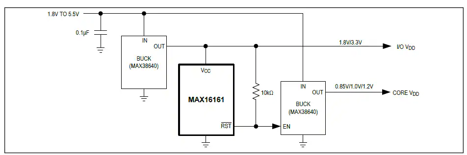
One of the basic tasks for a PMIC is sequencing two regulated DC rails to ensure that the power comes up to circuit functions in the proper order. For example, a processor core should be powered up, executing code, and functioning before any external-facing inputs and outputs (I/O) are enabled, as any “unmanaged” I/O could set output bits that are erroneous with undesired implications.
In this relatively simple case, the PMIC monitors the output of the first regulator (Fig. 1). Once the PMIC determines that its output rail has reached a predefined value (sometimes fixed by PMIC design, otherwise set by a user-selected resistor), the sequencing function is initiated. The PMIC then delays for a programmed period (usually user-set via a resistor) before enabling the second regulator. In this way, the second rail is never enabled until the first rail has stabilized and the functions it supports are fully powered.
Many of today’s designs have more than two DC rails, which requires more complex sequencing. For this reason, vendors offer quad-channel (and even higher channel-count) sequencers. The example IC in Fig. 2 combines both basic, high-accuracy supervisory functions and a four-channel sequencer.
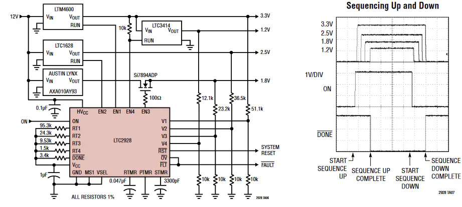
Using just a few basic external passive components, the IC allows designers to establish key parameters, including sequencing thresholds, order, and timing. The four power rails supported by the IC can be enabled in the required sequence. Additionally, device support is not limited to four channels; multiple devices can be cascaded to support additional devices and thus more channels. As a further benefit, the IC handles power-down sequencing, a complementary task to power-up sequencing and often just as important for system performance and integrity.
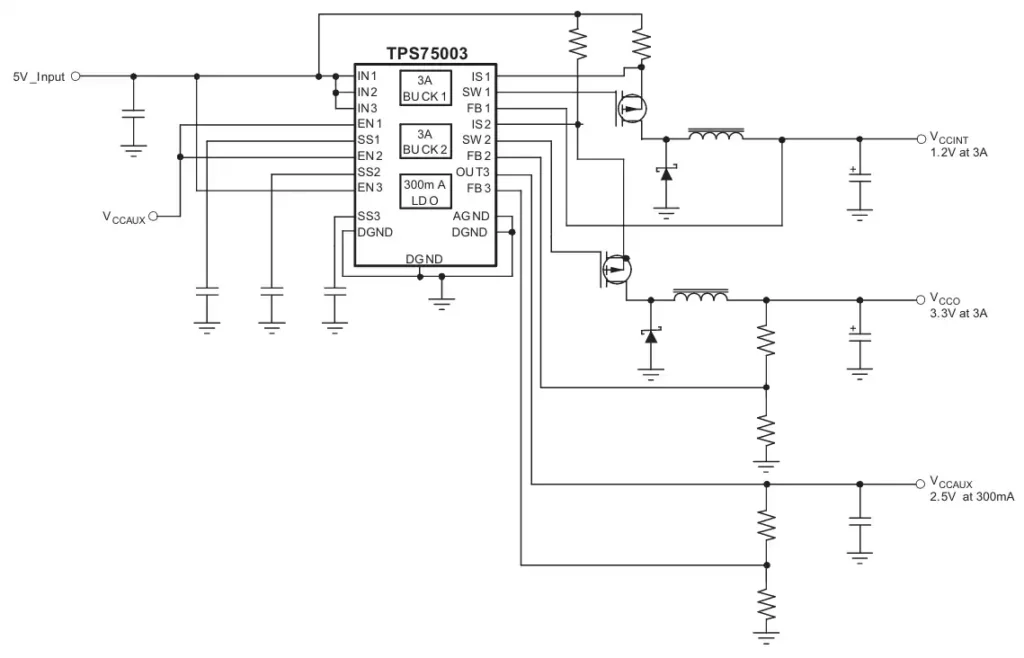
Although most PMICs are general-purpose devices, application-specific PMICs exist for widely used processors that have complex multi-rail requirements. Such PMICs eliminate the need for additional design time, cost, and associated risks. The configurable multi-rail PMIC in Fig. 3 has been validated to meet critical start-up requirements for specific FPGAs, including monotonic voltage ramp and controlled voltage-rail rise time.
Manage Start-up Inconsistencies
During system start-up, designers are concerned not only with whether voltage rails reach their nominal values, but also how they behave during the transition. Even brief irregularities in ramp profiles or timing between rails can lead to unintended behavior in downstream devices.
In multi-rail systems, different subsystems may respond to partial or intermediate voltage levels in different ways depending on their internal thresholds and initialization requirements. These varying responses can result in inconsistent start-up behavior, especially in processors and digital logic that depend on well-defined reset conditions before normal operation can begin. These issues can be difficult to isolate because they rely on interactions between regulator dynamics, load conditions, temperature, and component variation. As a result, systems may appear stable under one set of conditions but exhibit intermittent start-up issues in the field.
Modern PMICs address these challenges by tightly controlling reset signaling and validating supply conditions before enabling downstream circuits. By ensuring that devices are released from reset only after the voltage rails are within defined limits and the sequencing requirements are satisfied, these PMICs help eliminate unpredictable start-up behavior and improve overall system reliability.
Anticipate Imminent Failure
Many system designs assume that any input DC source to regulators is always stable and within specifications, but that is not always true. When instability occurs, it can compromise the performance of the entire power subsystem.
If these primary-side issues are not anticipated, power mishaps can induce undesirable effects on the system, including damage to the hardware. These failures in the system circuitry are hard to detect in advance. The potential for such failures is an added concern if the step-down DC-to-DC regulator has a wide acceptable input voltage range, which is increasingly the case due to improvements in regulator design and regulatory-driven performance mandates.
For this reason, a power-fail warning circuit (Fig. 4) can help anticipate the short-term future by detecting an imminent failure in the system’s upstream supply. This supervisory block IC and circuit generates a power-fail output (PFO) to serve as a basic early-warning system; the power-failure input (PFI) is the noninverting input to the power-fail comparator.
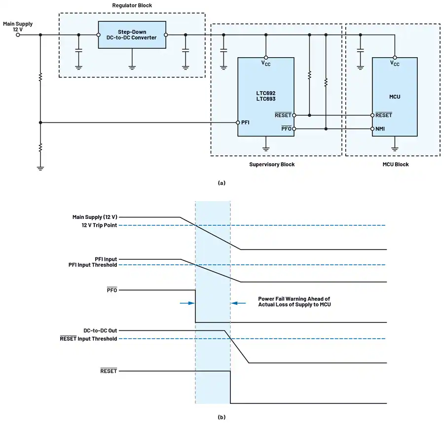
In turn, this PFO signal can be used as a high-priority interrupt to the processor, triggering it to execute critical tasks and shutdown procedures in the brief time window where output-rail power is still available due to capacitor “holdover” energy storage, before the DC/DC regulators drop out of regulation.
This holdover time is brief, typically on the order of just a few tens of milliseconds. However, it is sufficient for the processor to execute essential shutdown tasks, such as saving data and key register states in non-volatile memory and sending alert messages. The actual time available before power shutdown is determined by multiple factors, including the regulator subsystem’s design, the size of its output bulk capacitors, and the current drain on the power output.
Assess the Need for Battery Backup
Some applications incorporate batteries for backup power because they require continuous operation and must avoid data loss during power interruptions and outages. These batteries are switched into the supply-rail subsystem when primary power fails.[3]
A PMIC that also includes provision for battery-backup switchover follows some simple rules (Fig. 5). When the input supply (VCC) is present, it is routed to the output (VOUT). However, when VCC fails, the battery voltage (VBATT) is routed to VOUT instead.
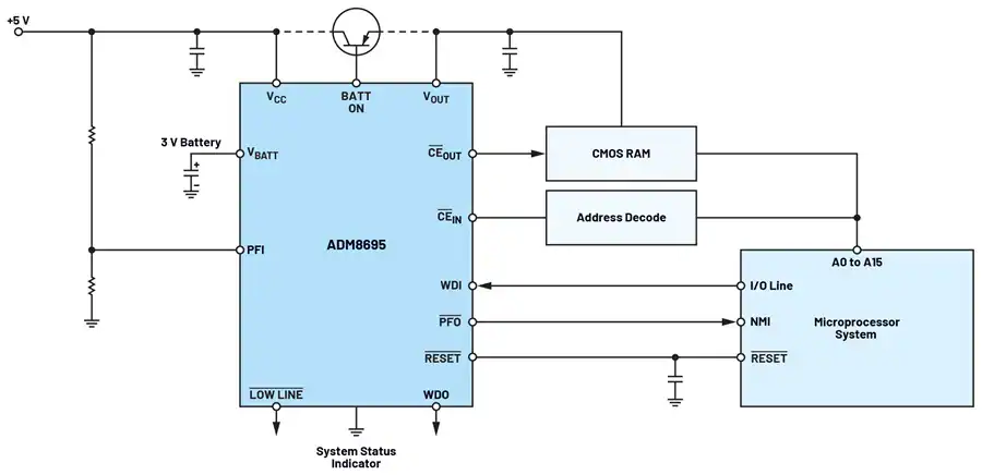
The switchover circuit compares the input supply voltage to the VBATT input and connects the output to whichever is higher. When VCC returns to proper regulation and exceeds VBATT, the BATT ON output goes low. The back-and-forth switchover is accomplished seamlessly and transparent to the load on the VOUT rail. Using a suitable PMIC eliminates voltage-rail losses due to diode drop, as would occur if the two sources—VCC and VBATT—were connected via the simple diode “voting” scheme traditionally used for power source switchover.
The VOUT line can supply limited current from VCC through an internal switch in the PMIC. If more current is required for larger loads, an external PNP transistor can be added, as seen in Fig. 5.
Conclusion
Modern PMICs include basic management functions, supervisory circuits, sequencers, power-fail anticipators, battery-backup switchover, and more. They offer a wide range of functions, features, and capabilities. Some are tightly focused on specific functions, such as multi-rail sequencing, while others incorporate a range of supervisory capabilities. PMICs manage the power subsystem to ensure consistent and reliable power-up, operational, and power-down modes.
As a result, uncertainties about power-rail transitions and performance are removed from design concerns. While some supervisory ICs and circuits include just a few of the features discussed in this article, others are available with many of these features built in and offered as a single component, providing a more comprehensive, complete solution.
Sources
[1] https://www.analog.com/en/resources/analog-dialogue/articles/soc-it-to-me-supercharge-with-pmic.html
[2] https://www.ti.com/lit/an/slva769a/slva769a.pdf
[3] https://www.analog.com/en/resources/technical-articles/choosing-off-battery-power-management-ic-for-automotive-electronics.html
By Bill Schweber. He is a contributing writer for Mouser Electronics and an electronics engineer who has written three textbooks on electronic communications systems, as well as hundreds of technical articles, opinion columns, and product features. In past roles, he worked as a technical web-site manager for multiple topic-specific sites for EE Times, as well as both the Executive Editor and Analog Editor at EDN. At Analog Devices, Inc. (a leading vendor of analog and mixed-signal ICs), Bill was in marketing communications (public relations); as a result, he has been on both sides of the technical PR function, presenting company products, stories, and messages to the media and also as the recipient of these. Prior to the MarCom role at Analog, Bill was associate editor of their respected technical journal, and also worked in their product marketing and applications engineering groups. Before those roles, Bill was at Instron Corp., doing hands-on analog- and power-circuit design and systems integration for materials-testing machine controls. He has an MSEE (Univ. of Mass) and BSEE (Columbia Univ.), is a Registered Professional Engineer, and holds an Advanced Class amateur radio license. Bill has also planned, written, and presented on-line courses on a variety of engineering topics, including MOSFET basics, ADC selection, and driving LEDs.