This project shows how to build an offline text-to-speech system using an ESP32-based IndusBoard Coin, TalkiePCM, and a MAX98357A I2S amplifier. Unlike cloud-based TTS systems, it generates speech locally without an internet connection or external API.
Offline Text-to-Speech for ESP32 provides a simple way to add voice output and audio feedback to electronic designs without relying on cloud-based APIs or a continuous internet connection. Most such devices rely on online APIs, where text is sent to the cloud and the generated speech is streamed or played back. However, these devices often fail to provide audio feedback when the internet connection is interrupted.
This project demonstrates how text-to-speech can be implemented both online and offline, free of cost and without relying on external APIs. The same approach can be used in a wide range of projects that require audio output or voice-based interaction. The design can also be adapted for any ESP-based board or other microcontroller board with I2S audio output capability.
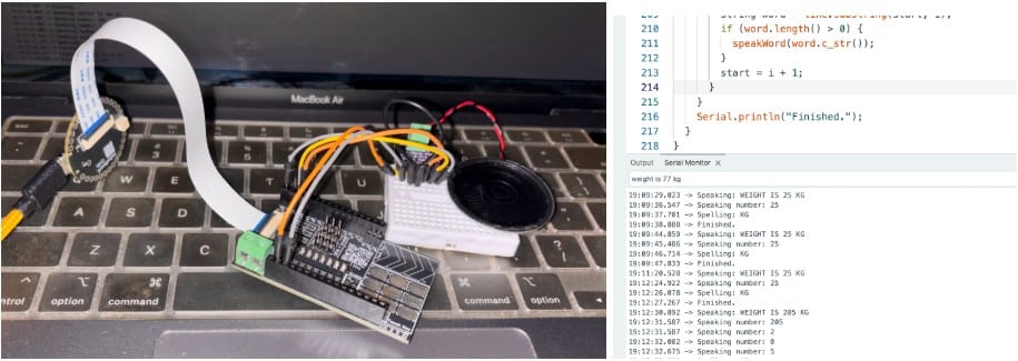
The design uses the IndusBoard Coin as the main controller. For audio amplification, the MAX98357A mono amplifier is used to drive the speaker. It receives digital audio data from the MCU through the I2S bus and amplifies it for audio playback.
Text can be entered through the Serial Monitor and converted into speech, or the code can be modified and integrated into other projects where text-to-speech output, voice-based interaction, or audio feedback is required.
Bill of Materials
| Component | Description | Quantity |
| IndusBoard Coin | WIFi MCU board | 1 |
| MAX98357 amplifier | I2S amplifier module | 1 |
| 8Ω speaker | Mini speaker for audio | 1 |
| USB C cable | For flashing firmware | 1 |
| 3.3V NimH or LiPo Battery / Power Supply | 3.3V 1A power supply | 1 |
Connection
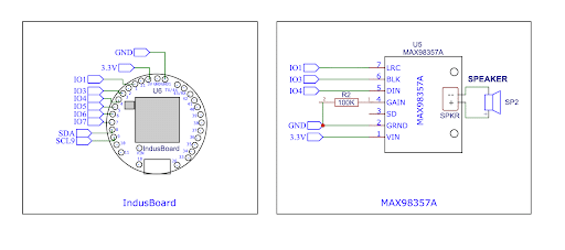
In this design, the MAX98357A I2S digital audio amplifier is used to generate clear audio output. The amplifier is connected to the I2S (Inter-IC Sound) interface of the development board. I2S is a digital communication protocol specifically designed to transmit high-quality audio data between integrated circuits. Unlike analogue audio signals, I2S transfers digital audio samples over dedicated data and clock lines, resulting in better audio quality and improved immunity to electrical noise.
The I2S interface typically consists of three main signals:
- BCLK (Bit Clock): Synchronises the transmission of individual audio bits.
- LRCLK (Left/Right Clock or Word Select): Indicates whether the transmitted data belongs to the left or right audio channel.
- DIN (Data Input): Carries digital audio data from the microcontroller to the amplifier.
The MAX98357A receives the digital I2S audio stream, performs the required digital-to-analogue conversion internally, amplifies the signal, and directly drives a speaker. Since the DAC (Digital-to-Analogue Converter) is integrated into the MAX98357A, no external DAC circuitry is required, making the overall design simple and compact.
One of the advantages of the IndusBoard Coin is its highly flexible GPIO configuration. Suitable GPIO pins can be assigned to the I2S peripheral through software or the ESP32 SDK. In this project, Pins 1, 3, and 4 are configured as the I2S interface for transmitting audio data to the MAX98357A amplifier.
Configuring the MAX98357A Audio Gain
The output gain of the MAX98357A can be configured using the GAIN pin. The amplifier supports five gain levels: 3 dB, 6 dB, 9 dB, 12 dB, and 15 dB.
The gain can be configured as follows:
- 15 dB: A 100 kΩ resistor is connected between GAIN and GND.
- 12 dB: GAIN is connected directly to GND.
- 9 dB: GAIN is left unconnected. This is the default setting.
- 6 dB: GAIN is connected directly to VIN.
- 3 dB: A 100 kΩ resistor is connected between GAIN and VIN.
In this design, a 100 kΩ resistor is connected between the GAIN pin and GND, configuring the amplifier for its maximum gain of 15 dB. This provides the highest output level and is suitable for portable voice-enabled devices and applications that require loud and clear speech output.
The following table shows the resistor configurations used to set the different gain levels of the MAX98357A.
| GAIN Pin Configuration | Resulting Gain |
| 100 kΩ → GND | 15 dB |
| Direct → GND | 12 dB |
| Floating (NC) | 9 dB |
| Direct → VIN | 6 dB |
| 100 kΩ → VIN | 3 dB |
Code for ESP32 Offline Text-to-Speech
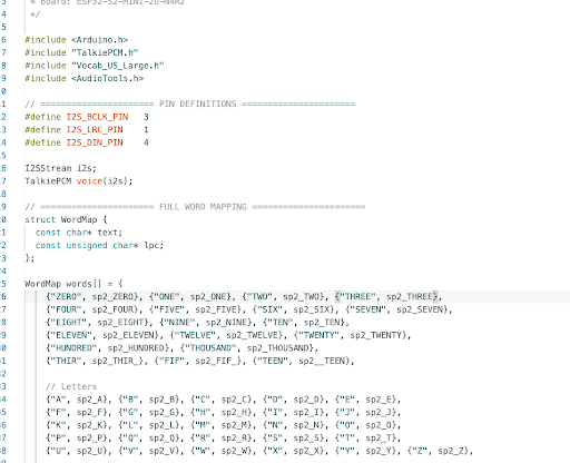
In this project, the TalkiePCM library is used along with the Vocab_US_Large vocabulary module. The Vocab_US_Large module contains more than 1,000 commonly used English words for text-to-speech applications. In addition to these predefined words, the library can also generate speech by combining letters and phonemes, allowing it to pronounce words that are not directly available in the vocabulary.
The following libraries need to be installed:
- TalkiePCM – Provides the text-to-speech engine and vocabulary support.
- Vocab_US_Large – Contains more than 1,000 pre-recorded words and speech data.
- AudioTools – Handles I2S audio processing and sends the audio output to an external I2S amplifier or speaker module.
Only the vocabulary required for a particular project needs to be included in the code. This helps reduce memory usage and keeps the program efficient.
For example, a talking voltmeter can include vocabulary related to numbers, volts, decimals, and other measurement terms. A greeting device or interactive assistant can include words such as “Hello”, “Hi”, “Welcome”, and “Good Morning”, along with other commonly used greeting phrases. Similarly, vocabulary can be included for sensors, measurement units, commands, menu options, or any other words commonly used in the application.
If a required word is not available in the provided vocabulary, custom speech data can be created and added to the vocabulary list for use in the project.
After adding the required vocabulary words and letter definitions to the code, the desired sentence can be created for speech output. The TalkiePCM library then converts the text into audible speech and outputs it through the connected I2S audio amplifier.
This approach can be used in a wide range of embedded projects, including talking voltmeters, smart assistants, industrial monitoring systems, medical devices, educational kits, navigation systems, IoT devices, and many other voice-enabled applications.
Note: The I/O pins used for I2S audio can be configured according to the I2S pins and ports available on the microcontroller or development board being used.
Testing ESP32 Offline Text-to-Speech
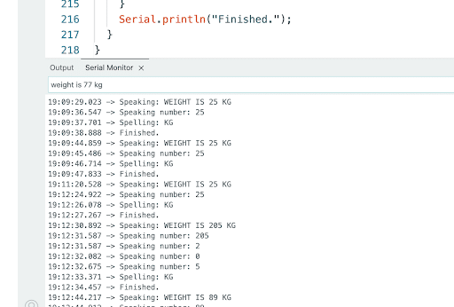
Connect the device to a USB port on a PC, then open the Serial Monitor and enter the text that the MCU needs to convert into speech. The MCU processes the text and outputs the generated speech through the I2S audio interface.