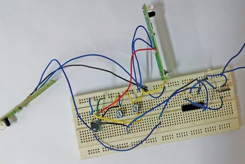
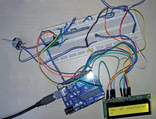
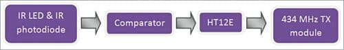
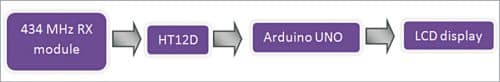
Information about the total number of persons present inside a building such as a hospital, shopping mall, or factory helps provide crucial information to the security/safety personnel during emergency situations. This article presents the implementation of an Arduino-based wireless visitors counter. The authors’ prototypes of the transmitter and receiver are shown in Fig. 1 and Fig. 2, respectively while their block diagrams are shown in Fig. 3 and Fig. 4.
Wireless Visitors Counter Circuit Diagram
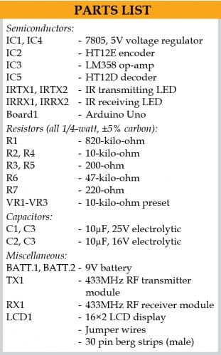
The main components used in this project are:
Arduino Uno board
Arduino Uno is an AVR ATmega328P microcontroller-based development board with six analog input pins and 14 digital I/O pins. The microcontroller has 32kB ISP flash memory, 2kB RAM, and 1kB EEPROM and can operate at a clock frequency of 16MHz. The Arduino Uno board (Board1) provides the capability of serial communication via UART, SPI, and I2C. In this project, the board is used for the receiver.

Digital I/O pins 12, 11, 7, 6, 5, and 4 of Board1 are used to interface with the LCD, and its digital I/O pins 2 and 3 are configured as interrupt pins.
HT12E
The 212 encoders are a series of CMOS LSIs generally used for remote control system applications. These are capable of encoding information consisting of N address bits and 12-N data bits. Each address/data input can be set to one of the two logic states. The programmed address/data are transmitted together with the header bits via an RF or an infrared transmission medium upon receipt of a trigger signal.
HT12D
The 212 decoders are a series of CMOS LSIs that are paired with HT12E encoders for use in remote control system applications. The decoders receive serial addresses and data from a programmed 212 series of encoders that are transmitted by a carrier using an RF or an IR transmission medium. These compare the serial input data three times continuously with their local addresses.
If no error or unmatched codes are found, the input data codes are decoded and transferred to the output pins. The 212 decoders are capable of decoding information that consists of N bits of addresses and 12 N bits of data. For a valid transmission, the address bits of both the encoder and decoder must be the same.
16×2 Character LCD
The LCD is used to display the total number of visitors entering the building. The LCD has sixteen columns and two rows for displaying data. The backlit LCD used here is interfaced with the Arduino in a 4-bit mode. The LCD pins RS, EN, D4, D5, D6, D7 are connected to digital I/O pins 12, 11, 7, 6, 5, and 4 of the Arduino Uno, respectively, on the receiver.
434MHz Modules
The 434MHz transmitter (TX) and receiver (RX) modules are electronic devices used to transmit and receive radio frequency signals between two devices. These modules are used widely in electronic design to avoid the complexity in designing radio circuitry. The carrier frequency of the modules used here is 434MHz.
LM358
This IC has two independent, high gain, and internally frequency compensated operational amplifiers which are designed specifically to operate from a single power supply over a wide range of voltages. Operation from split power supplies is also possible. In this project the LM358 is used as a dual comparator to generate a pulse when a visitor enters or leaves.
IR LED and Photodiode
The IR LED and IR photodiode pair are used to sense the entry or exit of a visitor. Two such pairs are used in this project—one at the entry gate and one at the exit gate.
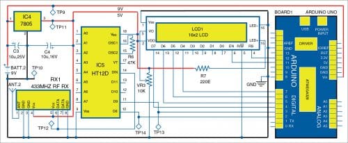
The circuit diagrams of the transmitter and receiver are shown in Fig. 5 and Fig. 6, respectively.
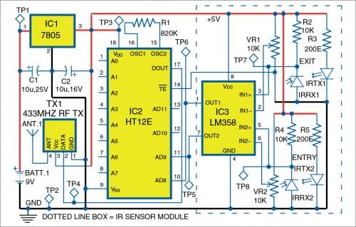
When a visitor enters the hall, he/she momentarily blocks the IR wave transmitted by the IR LED at the entry gate and some energy of the IR wave reflected back from the visitor’s body is sensed by the IR photodiode. The LM358 acts as a dual comparator and converts the momentary fluctuation detected by the photodiode to a pulse. The pulse is transmitted to the receiver side by the 434MHz transmitter. The two outputs of the comparator (one for entry and one for exit) are connected to two data pins of the HT12E encoder.
After successful wireless transmission, the pulses arrive on the data pins of the HT12D decoder on the receiver side. The two data pins of the HT12D are connected to two interrupt pins of the Arduino UNO board.
When a visitor passes through the entry gate, a pulse is generated at pin 7 (OUT2) of LM358, which is connected to the AD9 pin of HT12E. The same pulse is transmitted and appears on the D9 pin of HT12D on the receiver. The D9 pin is connected to interrupt pin 3 of the Arduino board. The interrupt subroutine executes and increments the visitor count by one. The operation is the same for the exit of a visitor except that separate data lines of HT12E (pin AD8) and HT12D (pin D8) are used and pin 2 of the Arduino is used as the interrupt pin.
The program running in the microcontroller of the Arduino monitors the interrupts and increments/decrements the visitors count and displays it on the 16×2 LCD. Arduino IDE is used for programming the Arduino Uno board.
Wireless Visitors Counter – PCB Design
Connect the Arduino board to the PC and select the proper COM port and board name from the Tools menu of the Arduino IDE. Then upload the source code visitor_counter_wl.ino to the Arduino board by clicking on the Upload button of the IDE.
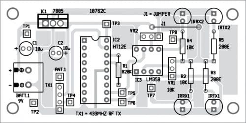
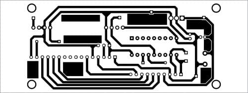
A PCB layout for the transmitter is shown in Fig. 7 and the layout of its components in Fig. 8. After assembling the circuit on PCB, connect a 9V battery across BATT.1.
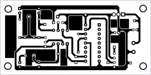
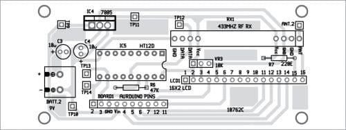
A PCB layout for the receiver is shown in Fig. 9 and the layout of its components in Fig. 10. After assembling the circuit on PCB, connect a 9V battery across BATT. 2.
Download PCB and Component Layout PDFs: click here
Download Source Code: click here
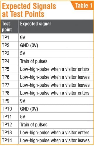
For troubleshooting, check the signals at different test points marked in Fig. 5 and Fig. 6 using a multimeter. The expected signals at different test points are listed in the Table.
Saikat Patra is passionate about electronics and MCU-based embedded system applications.
Shibendu Mahata is M.Tech (Gold Medallist) in instrumentation and electronics engineering from Jadavpur University. Currently, he is pursuing Ph.D. from NIT Durgapur. He is interested in MCU-based real-time embedded signal processing and process control systems.