 This project is designed using normally-closed reed switches connected to doors and windows and additional passive infrared (PIR) motion sensors to detect movement of a burglar or an unwanted intruder in your home. The security system can dial up to two phone numbers to alert you. It can also send text message to one of the numbers.
Circuit and working
Fig. 1 shows circuit diagram of the Arduino based GSM home security system. It works off a 12V power supply (connected across CON2). An Arduino microcontroller (MCU) requires only 5V but a GSM modem requires 12V. As Arduino Uno has an inbuilt 5V voltage regulator, a common 12V supply can be used for the whole system. It is built around two Arduino Uno boards (Board 1) and (Board 2), one SIM900 GSM module, TIP142 (T1, T2) and 2N2222 (T3-T5) transistors, magnetic reed switches, PIR motion sensors and a few other components.
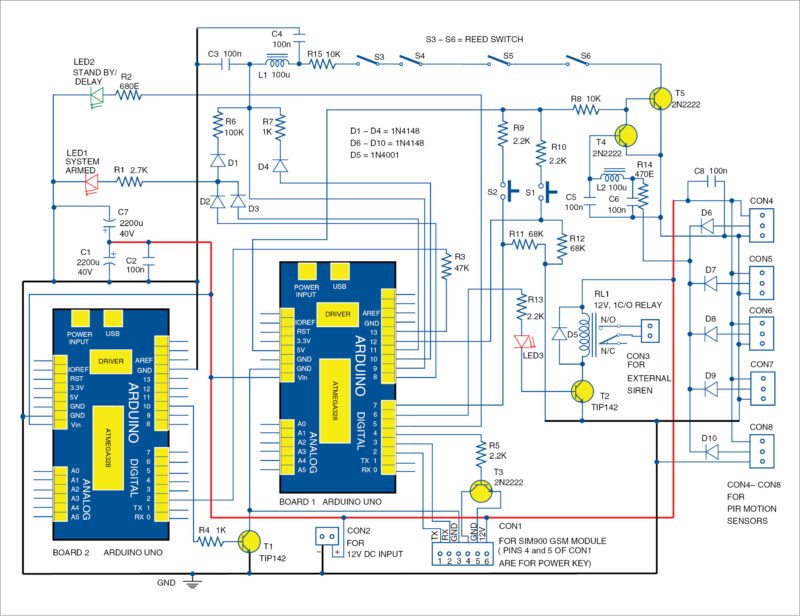
Brain of the circuit is Arduino Uno MCU board (Board 1). PIR sensors (connected across CON4 through CON8) detect motion, and output of the PIR sensor goes high when it detects any motion. The software constantly scans for a positive input at pin 9 (D9) of Board 1. When all the reed switches are closed and outputs of all PIR sensors are low, D9 is held low by T5.
A positive output on pin 8 (D8) or pin 11 (D11) of Board 1 is necessary to put the system in armed mode, which is indicated by LED1. As soon as one of the reed switches in the closed loop opens, or PIR sensors detect motion, logic level on D9 goes high via D8 or D11.
Pin 10 (D10) of Board 1 also goes high and latches D9 to 5V. Board 1 then commands SIM900 GSM module to send a text message and make six phone calls each to two different mobile numbers. You can simply ignore the calls and call your neighbour or a security guard to check on your home or premises.
After making a total of 12 phone calls, pin 13 (D13) of Board 1 goes high. It instructs Board 2 to cut off power supply to Board 1 and GSM module for five seconds. T1 switches off and on, thus resetting the system. Board 1 returns to standby mode, which is indicated by LED2.
The system can be activated again by sending an SMS. Each time the circuit is powered up, LED2 lights up to indicate that the system has entered standby mode. It also sends an SMS to your mobile phone that reads ‘Standby Mode.’
You can arm the system by sending SMS ‘$ON$’ and the circuit would reply back ‘Alarm On.’ The system now monitors all reed switches in the closed loop and output from all PIR sensors. It can be disarmed by sending SMS ‘$OFF1234.’ It would reply back ‘Alarm Off.’
A four-digit password is needed to disarm the alarm system by SMS. It can easily be changed by modifying the line in source code of Arduino1.ino sketch as shown below for reference.
[stextbox id=”grey”]if(inchar == ‘O’ || inchar == ‘F’
|| inchar == ‘F’ || inchar == ‘1’
|| inchar == ‘2’ || inchar == ‘3’
|| inchar == ‘4’) [/stextbox]
Before leaving home, you can also press push button S1 for 30 seconds instead of arming the alarm by sending an SMS. LED2 would start flashing. After 30 seconds delay, LED2 stops flashing and LED1 lights up to indicate that the system has been armed. Any unintentional intrusion by you at this point will trigger an alert. So be careful. Even otherwise, you will have 30 seconds to leave home and close the doors.
As shown in Fig. 1, T3 has been used to turn on GSM module via Arduino software. So there is no need to manually start GSM shield. RF chokes (RFCs) L1 and L2, along with decoupling capacitors C3 through C6, filter out stray radio frequencies and noise to avoid false triggering of the alarm system.
LED3 lights up when the alarm is activated. Board 1’s pin 6 (D6) has been used to activate relay RL1. A loud siren can be switched on via the relay to scare the burglar or intruder away. Reed switches can be mounted on door frames of entry and exit doors. Small magnets should be mounted on the doors themselves. When a door is closed, the magnet and the reed switch should be in close contact with each other. PIR sensors should be placed in each room, preferably on the wall and in view of the window.
Pressing switch S2 deactivates the alarm. The switch can be placed in a hidden location outside the house, but it is not recommended. Leave the house after pressing switch S1 and turn off the alarm via SMS when coming home from work in the evening.
Construction and testing
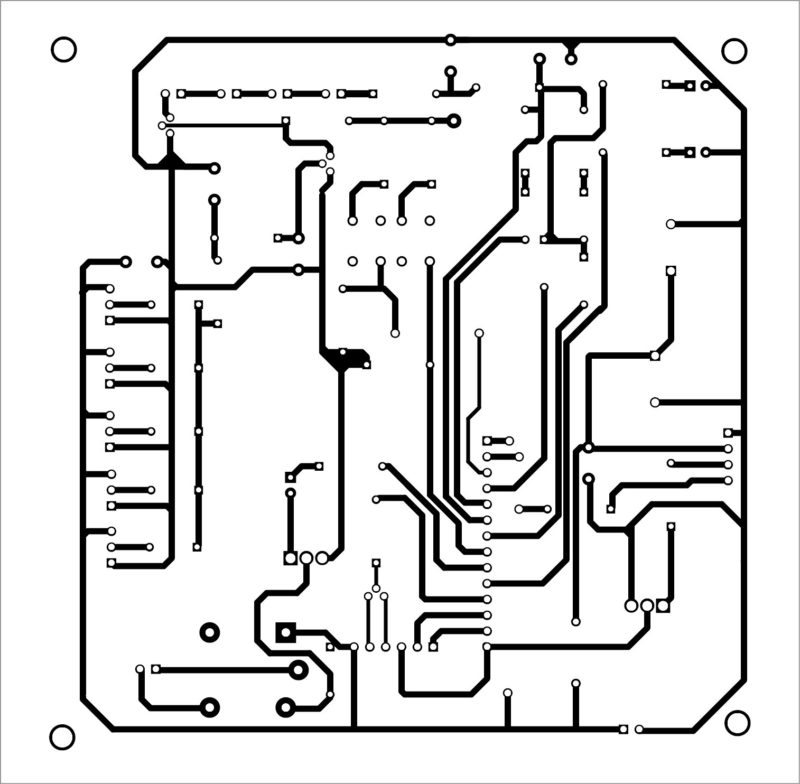
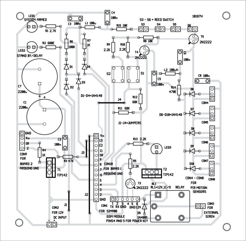
An actual-size, single-side PCB pattern for the Arduino based GSM home security system is shown in Fig. 2 and its component layout in Fig. 3. The circuit can be assembled on the PCB. It can fit easily inside most prototype/custom enclosures.
Download PCB and component layout PDFs: click here
Enter your primary mobile phone number to receive calls and SMS. This number is also used to send SMS commands like ‘$ON’ and ‘$OFF1234.’ Replace xxxxxxxxxx with your ten-digit mobile number in the following line of Arduino1.ino sketch:
[stextbox id=”grey”]String number =”xxxxxxxxxx”;
// 10 digit mobile number [/stextbox]
Enter the second number to receive alerts (phone calls only) in all the following lines under void call():
mySerial.print(“ATDT+ +91xxxxxxxxxx”);
As shown in Fig. 1, Arduino Board 1 and GSM module get ground connection through transistor TIP142 (T1). Also, very little drive current (<5mA) is required from Board 1. A 12V, 2A regulated power supply is recommended. It should be able to deliver 2A of current for the GSM module. An optional battery backup system can be added for additional security in case the burglar decides to turn off the electricity.
House the circuit in a plastic box and place it in a locked wooden cabinet. Make sure the GSM module has good signal strength. The alarm system can also be used to protect warehouses, shops, banks and office buildings.
Software
Software is written in Arduino programming languange. Arduino Uno Board 1 and Board 2 are programmed using Arduino IDE software. Atmega328P on Arduino Uno comes with a pre-programmed bootloader that allows you to upload a new code to it without using an external hardware programmer.
Connect both Arduino boards one by one to the PC and select the correct COM port in Arduino IDE. Compile the program (sketch). Then, select the correct board from Tools→Board menu in Arduino IDE and upload the sketch.
Arduino1.ino sketch is at the heart of the alarm system and carries out all major functions of the circuit. Arduino2.ino sketch is used to reset Board 1 and GSM module by switching off the power for a few seconds via T1. Please refer to source codes for details.
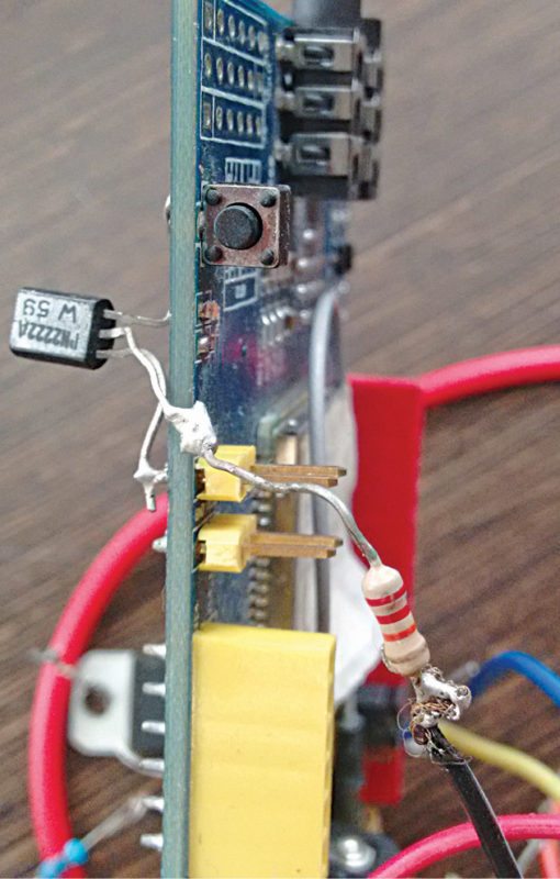
The author’s prototype is shown in Fig. 4.
Download source code
If you are looking for the difference between Microprocessor and Microcontroller, you can read it here.
This article is a part of the Top 15+ Microcontroller Projects. If you want to read more projects based on Microcontroller, can go through this article.
Joy Mukherji is an electronics hobbyist and a small business owner in New York, USA, and Lucknow, India. His interests include designing radio-frequency circuits


Which software you used for simulation of this project
No software simulation
sir i am using SIM900A GSM Module instead of SIM900 GSM Module is this module compatible with this circuit or i have to use SIM900 GSM module.
it is compatible. Go ahead with SIM900
is there is difference between SIM900 GSM and SIM900A GSM module.
Dear sir … I see that there is a difference between the scheme and the print layout with the components on it, which is correct. I would like to make an answer because it is an interesting projeckt.
Yours sincerely
Sir, your system is not working, thank you for not answering
Hi,
We are facing some technical issues with our website. Once sorted out we will surely reply you as soon as possible.
u mean the circuit isn’t working? Author here..
It is a nice and easy design but where can I find the source which operates this circuit?
Thanks
I’m sorry, That’s oK!
I could not convert PCB in pdf to Gerber file. Any suggestions?
Thanks again
Hi John,
Author here. You can construct the circuit on a a general purpose pcb. Source code is available at EFY. Google Electronics For You Source Codes.
Dear Joy, the source code is available on the last page of the project.
The source code is present on the last page of the project.
can i get source code in pdf format
hi,Where is the sim card?
SIM card goes into the SIM card socket at the back of the SIM900 gsm module .
Hi Joy
Thanks for the great project! I have searched the net for a while and finally stumbled upon your design and it is the closest to what I would want to build. I have a few questions:
1: I am not going to use the reed switches, how do I omit that part of the circuit without affecting the rest of the circuit and do I need to change the code?
2: I have two 12V alarm PIR sensors with NO contacts, can I use them as is or do I need to alter the wiring and or code?
PS: Is there any way of contacting you directly as I would have a lot of question during my build?
Thanks in advance!
Danie
Contact me directly joy226010 at gmail dot com
You can just short the wiring for the reed switches on the pcb. No need to change anything else. For PIR sensor, if it is normally Open contact , then connect one pin to positive 5V and the other to the PIR inputs on the alarm system . This way when the PIR sensor is triggered it will output a +5V and it should trigger the circuit. Just increase value of R14 to 1.5 K
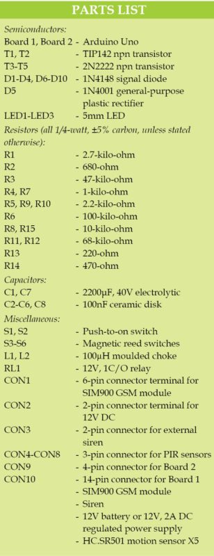
sir in schemetic arduino board 1 pin no 5 is connected with R8,R9 and R10 but pcb layout is not present.
and what is the value of r13 in schem is 2.2k and component list u give 220 ohm value please clear this
advance thanks for your reply
My Questions are:
1. How can i get the Arduino IC , because i know its a program based PIC.
2. I am currently using CCSC compiler, and arduino has its own compiler… therefore how can i achieve this.
Thank you
Arduino clone are easily available online. Look up Arduino nano board on eBay and sites like amazon. To complile and upload the code you will need to download the free arduino IDE program and install it on your computer. It’s available at http://www.arduino.cc
It is best and simplest project for the beginers
Can I make this project for comercial application?
Yes.
Can I use sim 800 module with same code?
Why your sim900 demand 12v supply?does it have RS232 interface?
Thanks and regards
max long wire can be used on reedsensor between ardunio.
max long (180m ) used its poissible
Yes you can use a long wire having a resistance of up to 15K or so. No problem! A 1Km or 1000m long copper wire with 0.5mm diameter has a resistance of 100ohm or so.
The 100uH RFC and 100n capacitors keep RF out so long wire is not a problem. Use any length you like.
I have done this project but now i’m facing an issue that the registered numbers are called one by one. I have regiestered six numbers in it. After calling those six numbers by the device only I can be able to send the message command to the device. But I need to send the turn OFF command in the middle of the phone call. Is there any corrections to fix it.? Please help me.! Thank you.!
Hi mail me [email protected]
You’ll need to reprogram the code. It can be done yes.