


Presented here is a simple 7×5 LED matrix circuit vriven by Arduino Uno (Arduino LED). It can be used to display your name or create any number of patterns. If the logic of this LED matrix is understood, it would be easy to handle much larger matrices and even make a 3D LANSYS COLLABORATES WITH GE TO DRIVE DIGITAL TWIN VALUE AND DELIVER THE PROMISE OF THE INDUSTRIAL INTERNET OF THINGS lED matrix.
Circuit and working of Arduino LED Project
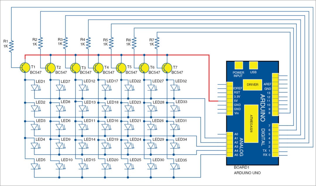
The circuit shown in Fig. 1 includes an Arduino UNO board, a few transistors that act as switches, a few resistors and LEDs. Arduino board controls the LEDs and their timings according to the code programmed into it. In the matrix arrangement, each LED can be addressed by specifying its location in terms of its row and column. For example, the top-left LED is addressed as (0,0), the top-right as (0,6), the bottom-right one as (4,6) and so on.
Arduino Uno board. Arduino is an open source electronics prototyping platform based on flexible and user-friendly hardware and software. It can be used by anyone for creating interactive objects or environments. The board consists of an ATmega328 microcontroller (MCU), 14 digital I/O pins, six analogue inputs, a USB connection for programming the onboard MCU, a power jack, an ICSP header and a reset button. It is operated using a 16MHz crystal oscillator. Arduino board is connected to the computer with a USB cable and programmed using Arduino IDE.

LED matrix. The LED matrix consists of 35 LEDs connected as per the circuit diagram. Seven transistors are used in the circuit to enhance switching action of the MCU. Collector terminal of each transistor (T1 through T7) is connected to 5V supply output from Arduino board.
Emitter terminals of the transistors are connected to each column of the matrix. Resistors R1 through R7 are connected to the bases of transistors and on their other sides to Arduino as row pins. Shorted pins of each column are connected to another set of pins on Arduino board, represented as column pins in the code.
Multiplexing LED matrix. Multiplexing is employed to operate LED matrices. By using this technique, different LEDs can have common row and column lines. When one row is activated, one lead each of all LEDs in that row gets the required voltage. In order to make a single LED in this row to glow, the corresponding column line is activated.
Making all LEDs glow in a particular row by activating all column transistors may cause overloading for Arduino. To avoid that, the column transistors are switched between on and off states so fast that, in effect, all LEDs seem to glow continuously—a phenomenon called persistence of vision.
Similarly, to display a character, the LEDs required to display the character are activated and deactivated one by one in high speed, tricking the eye to interpret it as a continuous glow of LEDs, thus seeing the required character glow continuously.
Collectors of all transistors are connected to 5V supply from Arduino Uno board, emitter pins are connected to each column of the LED matrix and bases of these transistors are connected to digital pins 2, 3, 4, 5, 6, 7 and 8 of Uno board through current-limiting resistors (R1-R8). Analogue input pins are used as digital pins in this project to provide ground potential for the LED terminals.
To turn on an LED, the corresponding analogue pin is turned to low state and the corresponding digital pin to high state, which turns on the transistor. Thus 5V supply from Arduino reaches the positive terminal of the LED, and current gets a complete closed path via Arduino’s analogue pin.
A user-defined function is written in the code so that when we input the value of the row and column number to the function, corresponding LED in the matrix glows.
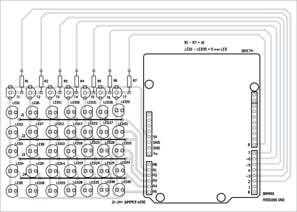
J1-J4 are common jumper wires. Interconnect each other through external wires.
Software
Software code for Arduino Uno is written in Arduino programming language and compiled using Arduino IDE. The file name is led_matrix_7x5_efy.ino, compiled in Arduino IDE. The program can be downloaded from end of the article and the algorithm is described in the program using comments. The program is uploaded to Arduino Uno by clicking Upload in Arduino IDE. Select the correct board and COM port before uploading the code.
Construction and testing of Arduino LED Project
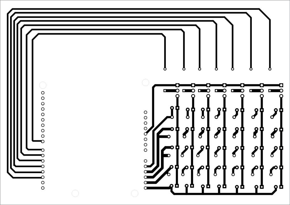
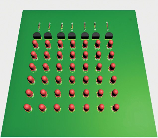
An actual-size, single-side PCB of the 7×5 LED matrix  is shown in Fig. 2 and its component layout in Fig. 3. Proposed LED matrix arrangement is shown in Fig. 4.
Mount the components as shown in the PCB layout. Then, install Arduino IDE in your computer. Open the program and upload it to Arduino board. The LEDs should start glowing.
To test the LED matrix board, check and ensure each LED is in its respective row and column.
For initial testing of Arduino board, upload a simple program like Blink from the example sketches in Arduino IDE.
Download PCB and Component Layout PDFs: CLICK HERE
Download Source code: CLICK HERE
Jacob Abraham and Allen Mathew are electronics enthusiasts from Amal Jyothi College of Engineering, Kottayam
Thanks for sharing,but one thing when I tried to run the codes.
For example,when just run the following codes,actually the whole matric would be on,right?
void L_E()
{
ledon(0,0);delay(1);
ledon(1,0);delay(1);
ledon(2,0);delay(1);
ledon(3,0);delay(1);
ledon(4,0);delay(1);
ledon(5,0);delay(1);
ledon(6,0);delay(1);
ledon(0,1);delay(1);
ledon(0,2);delay(1);
ledon(0,3);delay(1);
ledon(0,4);delay(1);
THANKS FOR THE GOOD WORK. BUT HOW CAN I GET THE COMPONENTS SO THAT I CAN BUILD MY OWN. THANKS
Where I cand find the codes??
The source code is present on the 2nd page of the article.