 In restaurants, auditoria and even homes, many a times we forget to switch off the wash basin mirror lamp after use. The circuit given here automatically switches on the wash basin mirror lamp whenever you stand in front of it and switch off the same after you move out, thereby saving energy.
The IR LEDs transmit modulated 38kHz square wave pulses, which are reflected back to the receiver sensor by the person standing in front of the mirror. When the receiver sensor detects IR rays, it energises the relay for a predetermined delay period, which switches on the washbasin lamp for that period.
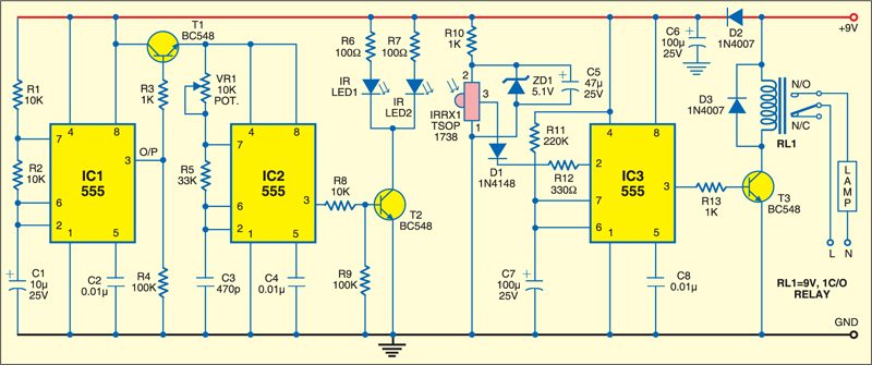
 Fig. 1 shows the circuit of the automatic washbasin lamp controller. It consists of two sections, viz, infrared transmitter and receiver. The transmitter section is built around IC1 and IC2, while the receiver section is built around IC3.
In the transmitter circuit, IC1 functions as an astable multivibrator and produces pulsed output at 5 Hz. The 5Hz pulsed output enables IC2 through transistor T1. IC2 is also configured as an astable multivibrator that outputs 38kHz square wave. The output frequency of IC2 can be adjusted through the variable 10-kilo-ohm potmeter. The output of IC2 is fed to two IR LEDs through driver transistor T2.
The receiver circuit comprises IR sensor TSOP1738, switching diode 1N4148 (D1), timer IC 555 (IC3), relay-driver transistor BC548 (T3) and associated components. Whenever the sensor receives IR radiations, it triggers IC3, which is wired as a monostable multivibrator with a time period of approximately 24 seconds. The time period can be changed to any desired value by changing the values of R11 and C7. The output of IC3 is connected to relay-driver transistor T3.


Transistor T3 conducts for 24 seconds when the sensor receives modulated 38kHz IR pulses from the IR transmitter. This energises relay RL1 and the mains AC terminal for the mirror lamp connects to the normally-open (N/O) contact of relay RL1, turning on the wash basin mirror lamp or 24 seconds. Thus the wash basin mirror lamp is switched on as and when a person stands in front of it. Otherwise, it remains off.
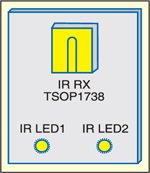
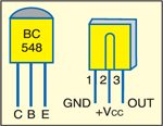
The complete circuit works off regulated 9V power supply. Assemble it on any general-purpose PCB, enclose in a suitable cabinet and mount behind the wash bashin mirror. Mount the IR LEDs and receiver sensor above the wash basin as shown in Fig. 2. Fig. 3 shows pin configurations of transistor BC548 and sensor TSOP1738.


which relay is used