


 Make your washbasin tap work automatically when you put your hands just below the water tap outlet. This infrared-based automatic washbasin tap controller system detects any interruption of the IR rays by your hands or utensil and water automatically starts flowing out of the tap.
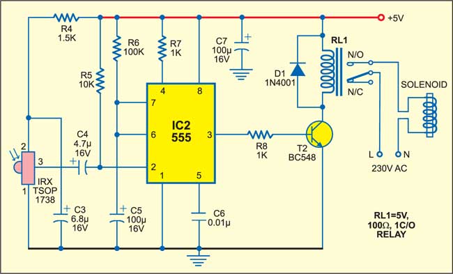
Automatic washbasin tap controller circuit
The circuit is built around 555 timers and comprises transmitter and receiver sections. Both the transmitter and the receiver work off 5V DC. The IR rays continuously emitted by the transmitter fall on the receiver. As soon as an obstacle comes in between the receiver and the transmitter, interrupting the IR rays, the output of the IR sensor goes low momentarily to trigger the timer circuit in the receiver and water comes out for eleven seconds through the tap.
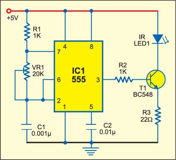
The transmitter is built around timer IC 555, which is used as an astable multivibrator to generate around 38 kHz frequency (see Fig. 1). The timer output is fed to transistor T1, which drives the IR LED (LED1). Note that IR LED1 must be properly oriented towards the IR sensor module of the receiver circuit. Its transmission wavelength of 900 to 1100 nm lies in the peak receptivity range of TSOP1738 receiver module.

The receiver circuit comprises the sensor module, monostable timer and relay driver circuit (see Fig. 2). The sensor module TSOP1738 is sensitive to IR radiation modulated at 38 kHz. Its normally high output goes momentarily low when any IR radiation is detected or interrupted.
Circuit operation
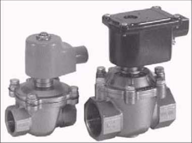
When IR rays falling on the receiver are interrupted, the sensor output goes low momentarily to trigger timer IC2. The output of the timer goes high for eleven seconds and the relay drives the solenoid. During this time period, energisation of the solenoid lifts up the valve fitted in the pipe to let water flow out of the tap. Solenoid valves used specifically for this purpose are shown in Fig. 3.
The relay driver circuit consists of resistor R8, transistor BC548 (T2) and free-wheeling diode D1. Diode D1 protects the relay from damage by high voltages generated by the back emf when the relay is de-energised.
The time period for which the timer goes high can be calculated as follows:
Ton=1.1 R6C5=1.1×100×103×100×10–6=11 seconds
Construction & Testing
Use shielded wires or leads for installing the IR LED and the IR sensor at opposite sides of the washbasin. Install the IR LED and IR sensor around half a metre apart such that the IR rays transmitted by the IR LED directly fall on the IR sensor. Now switch on the power supply to the circuit.
When you put your hands between the IR LED and IR sensor, the relay energises to make the solenoid open up the valve and water flows out of the tap.
Feel interested? Check out other electronics projects.

Hi i want to control solenoid valve 220 valve using infrared sensor .For supply i will use adapter.
Kindly elaborate your query.
how to decrease time period of 11second in cercuit…..?
by changing the registance and capacitor value of the IC2 and time period can be calculated by using the formula 1.1*R*C
may i get in touch with the developers of this project. my email [email protected]
i would like to build a circuit that will automatically flushes the toilet, by using a sensor, comparator, 555 timer and a solenoid
Hi
I tried building the circuit but I subtituted BC548 with BC558 and swapped the Collector and the Emitter accordingly for BC558 is PNP. The receiver circuit activate the solenoid anytime I connect the power. But the Emitter circuit is not activating the IR LED, can you please help
It will not work in that way. Pin orientation for BC548 and BC558 are same, the difference is in the internal part. Please use BC548 as shown in the circuit.
Hi,
we want 1500 nos of solenoid valve with UV sensor to operate wash basin tap for our projects, we have the circuit diagram and prototype, can you please make for this , please reply as your earliest.
regards
Sushil
HELLO Sir,
We do have our own electronic production unit in Madurai.We are ready to produce and supply as per your requirements.Please send us all the details.
What is the use of resistor R4,R5 and capacitor C4,C3 in reciever circuit??
can you supply me the sensor circuit? plz post mee message