


This article describes the basic installation of an RFID and password-based door access control system. Access control systems allow only authorized persons to enter or exit the premises.
Access control systems often include locks, turnstiles, biometric scanners, face recognition devices, RFID readers, and boom barriers.
Table of Contents
Required Parts
The materials required for this access control system include:

- Magnetic lock with a mounting bracket (fail-safe type lock)
- DC power supply adaptor or switched-mode power supply (SMPS) (12V, 3A)
- Access control reader
- Exit push button
- Connecting wires (Cat 6 or copper wires, as required)
Access Control System: Wiring Installation Diagram
The block diagram of the access control system is shown in Fig. 1. It is built around a magnetic lock with mounting brackets, a 12V SMPS/adaptor for the power supply, an access control device, an exit push button, RFID tags, cables.
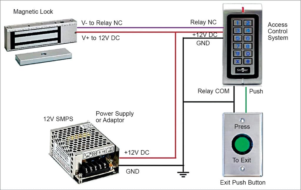
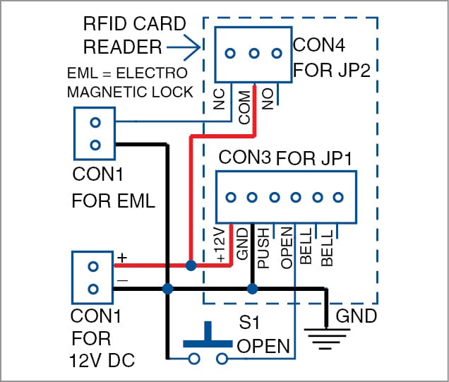
It includes 3- and 6-pin connectors along with 3- and 6-wire cables to connect the access control device. The complete wiring diagram for the project is shown in Fig. 2.
Relay Circuit Connections
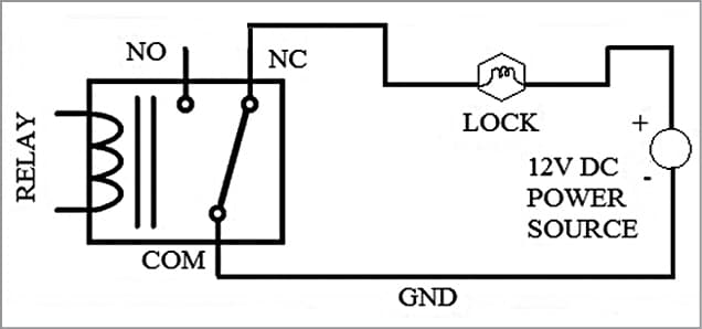
Before installing, let’s understand the relay concept used in most access control systems. The relay (refer to Fig. 3) has three contacts: NO, NC, and COM, which are usually referred to as normally open, normally closed, and common terminal, respectively.
COM usually remains connected to the NC terminal. When the relay is activated, the COM terminal gets connected to the NO terminal, breaking away from the NC terminal.
Most of the access control readers, push buttons and locks have an inbuilt relay circuit for the desired connections.
Access Control Device
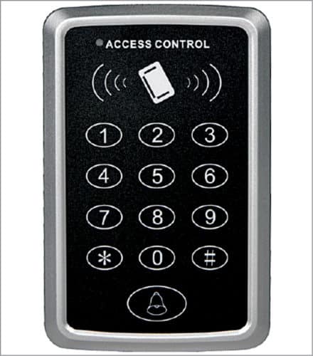
The access control reader and fail-safe magnetic lock are key components for this RFID-based installation. The standalone access control device (model number SA32-E) used in this project is shown in Fig. 4.
It is a contactless RFID smart card reader and password verification device. It enables three verification modes (RFID card only, PIN only, and card & PIN) to ensure maximum safety and flexibility.
With one relay output (optional) and a push-button (low) output, one door button port, and one doorbell port, the device is simple but effective for use in residential housing, offices, and other public facilities.
When the magnetic lock is directly connected with a +12V supply and ground (GND) across the terminals, the lock functions normally (that is, the door remains locked).
Note that there are two main types of magnetic locking devices: fail-safe and fail-secure.
Fail-secure locking device gets locked when the power is off.
Fail-safe locking devices are locked when the power is on and gets unlocked when the power goes off. This project uses a fail-safe locking device.
Configure the locking device to automatically unlock with an RFID tag or biometric scan, and relock after a preset time to prevent tailgating.
Most of the biometric devices or access control readers are pre-equipped with a relay circuit on board. The circuit is designed in such a way that the GND rail from the power supply/adaptor connects through the NC and COM terminals of the reader and exit push button.
The +12V DC from the adaptor or SMPS is connected directly to the electromagnetic lock as shown in the block diagram (refer to Fig. 1).
Most of the magnetic locks and access control readers are pre-equipped with timers for locking and unlocking time delays. Generally, presets are found on the PCB board, which can be adjusted for locking or unlocking time delays.
Door Access Control System Working
When a pre-registered user or authorized person tries to open the door using an RFID tag (card) or password or biometrics, the relay circuit gets activated and the COM terminal gets disconnected from the NC terminal for a while. That is, the COM terminal gets connected to the NO terminal.
Hence, the 12V DC power supply is disconnected from the magnetic lock for a few seconds (depending on the preset time delay). So the magnetic lock gets unlocked when the power goes off. This action allows the door to open.
Again, when the user presses the exit push button, the relay gets activated and is forced to connect COM with NO terminal. The supply gets disconnected from the magnetic lock and it gets unlocked, and the door gets opened again.
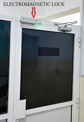
Basically, the access control device is to be installed near the door outside the room and the exit button is to be installed near the door but inside the room. The electromagnetic lock installed on the glass door is shown in Fig. 5.
Some exit push buttons will have inbuilt relay circuitry, which must be given an external power supply. In that case, it is preferred to use a 12V, 3A power supply.
RFID Card Access Control
Some details on the RFID card/tag are given here. Every RFID card/tag has a unique number. When the tag is swiped across the RFID reader, the access control system prompts you to enter a password. The default password is 123456.
To change the password, press #123456#0987654#987654# on the access control keypad. If you hear a long beep, it means the password is successfully registered. To add a new RFID card, press #987654#1 on the input keypad. Swipe the tag/card near the reader followed by pressing the # key.
Download Source Code
Now as we discussed the basics of access control system installation, let’s try RFID-based projects.
S. Aravind is B.Tech and currently working as an extra-low voltage systems engineer in Oman
This is a valuable article, In which people better understand to Know about the Basic installation of Access Control Systems. Keep sharing in the future also such great information. Thankyou
Thank you for your valuable feedback.