


 Rechargeable batteries should not be discharged below a certain voltage level. This lower voltage limit depends upon the type of the battery. This simple battery low indicator circuit can be used for 12V batteries to give an indication of the battery voltage falling below the preset value. The indication is in the form of a flickering LED.
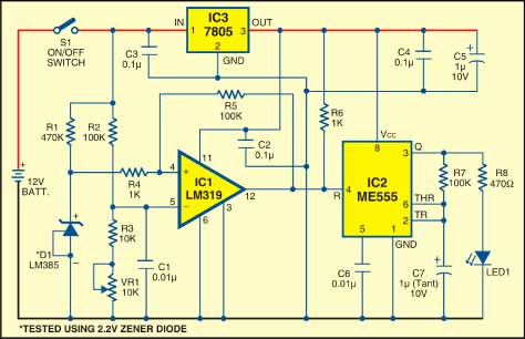
At the heart of the circuit is voltage comparator IC LM319 (IC1). It is a dual comparator with a TTL-compatible output. We have used only one comparator here. A reference voltage of 1.2 volts generated by band-gap reference diode D1 (LM385) is applied to the non-inverting input (pin 4) of the comparator. The inverting input (pin 5) of the comparator is fed a voltage generated from the potential divider arrangement built around resistors R2 and R3 and preset VR1. That means, if you are using a 12V battery and want an indication as soon as the battery voltage goes below 10.5V, adjust the voltage at the inverting input using reset VR1 so as to get a voltage of 1.2 volts (with battery voltage at 10.5V).
Initially, when the battery is fully charged, the voltage at the inverting input of IC1 is higher than the non-inverting input and output pin 12 of IC1 remains low. The reset pin (pin 4) of IC2 connected to pin 12 of IC1 also remains low and the astable multivibrator built around IC2 does not oscillate. As a result, LED1 does not flicker.

When the battery voltage falls below 10.5V, the voltage at the inverting input of IC1 becomes lower than the non-inverting input and the output of IC1 goes high. The reset pin of IC2 connected to pin 12 of IC1 also goes high and the astable multivibrator built around IC2 starts oscillating. LED1 flickers to indicate that the battery voltage is low and the battery needs to be charged before further use. Both IC1 and IC2 operate off regulated +5V DC generated by voltage regulator IC 7805 (IC3).
Assemble the circuit on a general-purpose PCB and enclose in a suitable cabinet. Mount LED1 and switch S1 on the front side of the case. Connect a 12V battery to check its voltage level.
More interesting projects available here.

Hi Raj,
recently I purchased the items and prepare the setup. It is running fine when threshold voltage is 9v. But my required threshold voltage is 11v. In my case I need to change in circuit, Can you please help me for that?