 BODMAS rule is an acronym to help children to remember the order of operations in calculations.. The term BODMAS stand for bracket, of, division, multiplication, addition and subtraction and the BODMAS rule is a mnemonic for the hierarchy of various arithmetical operators. A mathematical expression may involve a number of operators, but only one of them must be carried out first. The order of priority, as we are familiar from school days, follows: ‘Bracket’ followed by ‘of,’ ‘division,’ ‘multiplication,’ ‘addition’ and then ‘subtraction’ in that order.
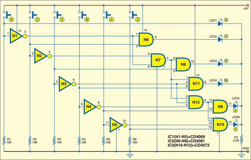
BODMAS rule circuit
As a teaching aid to the beginners learning arithmetic, this circuit would be very helpful. This circuit checks for any wrong answer and wrong order.

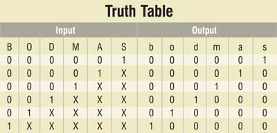
Truth table of the mentioned priority checker is shown here. The upper-case letters in the table (B, O, D, … etc) denote inputs, while the lowercase letters (b, o, d, … etc) denote outputs.
If an input variable is at logic ‘0’ it means that particular operation is absent in the mathematical expression, while if an input variable is at logic ‘1’ it is present in the mathematical expression. The expression may contain any number of operations (any number of inputs may be at logic ‘1’), but only one output will be at logic ‘1.’ This means a particular operation has the highest priority and must be carried out first. (X’s in the truth table indicate the ‘don’t care’ inputs, i.e., they may be at logic ‘0’ or logic ‘1.’)

From the truth table, you can easily arrive at the following Boolean equations:
b = B
o = B. O
d = B. O. D
m = B. O. D. M
a = B. O. D. M. A
s = B. O. D. M. A. S
Circuit operation
The logic circuit of the priority checker comprises NOT and AND gates, LEDs and a few resistors. The working of the circuit is as simple as its structure. Pressing any of the six micro-switches, named ‘B,’ ‘O,’ …, ‘S,’ makes the corresponding variable high (logic 1). The glowing of a particular LED, bearing the same name as the output variable, will indicate its top priority.
For example, pressing ‘B,’ ‘M’ and ‘A’ simultaneously will cause only LED ‘b’ to turn ‘on,’ indicating that the bracket operation has the highest priority. If ‘M’ and ‘A’ are pressed, LED ‘m’ will glow, indicating that ‘multiplication’ is to be carried out prior to ‘addition.’
The article was first published in October 2006 and has recently been updated.


pcb layout please