 Most of the low-power UPS systems available in the market do not have the facility to shut down the PC before they turn off automatically due to low battery. Some of them have the facility but they require software for the same.
Here we give an ‘add-on’ circuit for UPS that will hybernate the PC automatically before UPS turns off due to low battery voltage. It requires no enabling software.
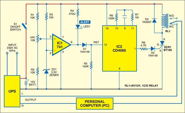
The circuit consists of comparator IC 741 (IC1) followed by a short-duration positive pulse generator using a 14-stage ripple-carry binary counter/divider and oscillator IC2. Usually, the voltage at the non-inverting (positive) input terminal of IC1 is high compared to the inverting (negative) input, so the output of the comparator is high. This high output of IC1 is used to reset IC CD4060 (IC2), which is a 14-stage ripple counter.
As the UPS battery voltage goes below the preset value, the non-inverting terminal voltage of comparator IC1 at pin 3 reduces. In this circuit, as the battery voltage goes below 9.5V, the voltage at pin 3 of IC1 reduces below 3.3V and the output of the comparator at pin 6 goes low to light up LED1, indicating to the user that his computer is going to hybernate within a preset time (around 3 minutes).
The low voltage level at pin 12 of IC2 enables it to oscillate and the counter starts counting, resulting in a high output at its pin 1 after 3 minutes. This high output is used to fire SCR1, which energises relay RL1. The relay will de-energise only when the power supply for the circuit is switched off manually through S1.
The circuit is assembled on a small PCB and connected to the UPS battery terminals. The hybernation-activation voltage of the circuit is set above the cut-off voltage of the UPS. (If the cut-off volatge of the UPS is 9.5 volts, set the hybernation-activation voltage level as 10 volts.) The circuit is fixed inside the UPS cabinet. Switch S1 and LED1 are wired up to be on the front panel of the cabinet.


