
An N20 motor is a compact DC geared motor widely used in robotics and DIY applications. By combining a small DC motor with an integrated gearbox, it delivers high torque in a compact form factor. Motor drivers are essential components in robotic systems, enabling precise control of motor speed and direction. Integrating motor-driver circuitry and sensor interfaces directly onto the robot chassis simplifies construction, reduces wiring complexity, and improves overall reliability.
The proposed system integrates the motor-driver circuitry directly into the robot chassis PCB, creating a compact, self-contained robotic platform. It enables precise control of the robot’s direction, speed, and individual wheel movement through a single FPC (flexible printed circuit) cable, simplifying assembly and reducing the number of interconnections.
POC Video Tutorial
The system supports various control methods, including Wi-Fi and other communication interfaces. Conventional robot designs often require separate connections for motor drivers, batteries, displays, sensors, and microcontrollers, leading to complex wiring and longer assembly times.
To overcome these limitations, a compact robot PCB has been developed that serves as both the main circuit board and the structural chassis. N20 motors can be mounted directly onto the PCB alongside the motor driver, battery interface, power management circuitry, and display connections. The board supports surface-mount assembly and includes provisions for additional servo motors, further reducing wiring requirements.
Despite its compact form factor, the complete robot chassis measures only about 4cm. The PCB includes an FPC connector and header pins for easy interfacing with external microcontrollers. When used with the IndusBoard Coin, the controller can be connected directly through a single FPC cable. For other microcontrollers, only four motor-control signals are required, and a custom FPC adaptor can be implemented if needed.
The system is based on the DRV8833 dual motor driver IC and includes two servo connectors and two I²C expansion connectors. These interfaces allow direct connection of displays and sensors without additional wiring. A dedicated battery input is provided, and configurable solder jumpers allow users to either share a common power source between the motor driver and microcontroller or use separate supplies for greater flexibility.
In addition to simplifying control and connectivity, the PCB also serves as the robot’s structural chassis. It incorporates integrated N20 motor-mounting slots and four expansion-mounting holes, enabling easy stacking of additional layers and modules such as lidar, radar, cameras, displays, and other sensors. This modular architecture allows the robot to be customised for a wide range of applications while maintaining a compact footprint.

Fig. 1 shows the author’s prototype and the developed PCB. The components required to build the integrated motor-driver robot chassis are listed in Bill of Materials table.
| Bill Of Materials | |||
| Component/Part Description | Designator | Package/Footprint | Quantity |
| 10µF capacitor | C1 | C0805 | 1 |
| 2.2µF capacitor | C2 | C0805 | 1 |
| 10nF capacitor | C3 | C0805 | 1 |
| DRV8833PW dual motor driver IC | U1 | HTSSOP-16 (5.0mm×4.4mm, 0.65mm pitch) | 1 |
| DRV8833 dual motor driver module | U2 | DRV8833 motor driver module | 1 |
| 2-pin screw terminal | CON1 | Screw_terminal_2PIN | 1 |
| 24-pin FPC connector (XW0520012-240R-001) | FPC1 | FPC-SMD, 24P, 0.5mm pitch | 1 |
| 4-pin header | H1, H2, H5 | Header_4PIN_VGT | 3 |
| 3-pin header | H3, H4 | Header_3PIN_VGT | 2 |
| N20 DC geared motor | M1,M2 | N20_DC_Motor | 1 |
Designing the system
Fig. 2 shows the circuit diagram of the integrated motor-driver robot chassis system. The system is built around the DRV8833 dual H-bridge motor-driver IC, which provides independent control of two N20 DC geared motors while integrating power distribution and sensor connectivity on a single PCB.
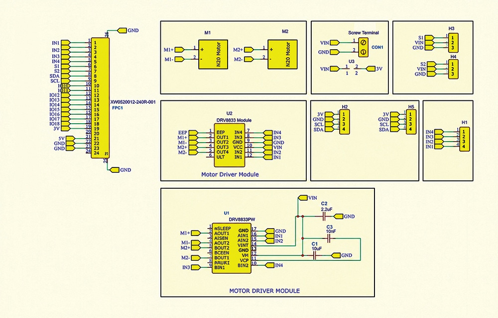
Power is supplied via the screw terminal (CON1), while a 24-pin FPC connector serves as the primary interface to an external controller, such as an ESP32 or an Arduino. The FPC cable carries motor-control signals (IN1-IN4), I²C communication lines (SDA and SCL), GPIO signals, sensor inputs, and power rails, greatly simplifying wiring and assembly.
During operation, the controller generates logic and PWM signals that are applied to the DRV8833 inputs. The motor driver converts these signals into high-current outputs to drive the two motors in forward, reverse, brake, or stop modes, enabling precise control of the robot’s speed and direction. Additional connectors are provided for sensor integration and future expansion, making the platform suitable for a wide range of robotics applications.
The system employs the DRV8833PW dual H-bridge motor driver in a compact HTSSOP package. The device operates from a motor-supply voltage of 2.7V to 10.8V and can deliver up to 1.2A of continuous current per channel, with peak currents of up to 2A. Motor speed is controlled using PWM signals, while motor direction is determined by the logic states applied to the input pins. The IC also includes a low-power sleep mode (nSLEEP) and a fault output (nFAULT) that provides protection against over-current, over-temperature, and under-voltage conditions.
As shown in Fig. 2, the 10µF, 2.2µF, and 10nF capacitors provide bulk decoupling, supply filtering, and charge-pump stabilisation, ensuring reliable operation of the motor driver. The main motor supply is connected through CON1 and distributed via the VIN rail. A solder jumper allows VIN to be linked to the 3.3V rail, enabling both the motors and the controller to be powered from a single battery when required.
The PCB also includes dedicated servo connectors, with signal lines routed from available GPIO pins and power supplied directly from the VIN rail. Two I²C expansion connectors are provided for easy integration of modules such as IMUs, distance sensors, environmental sensors, OLED displays, and other I²C-compatible peripherals.
By integrating motor control, power distribution, sensor interfaces, and mechanical mounting features onto a single PCB, the system provides a compact, modular, and easy-to-assemble robotic platform with minimal wiring requirements.
PCB design
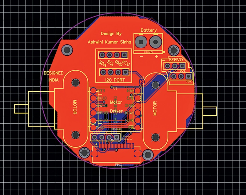
After finalising the schematic (Fig. 2), the PCB layout was developed. The DRV8833 motor driver is positioned near the centre of the board to optimise signal routing and ensure efficient power distribution. The N20 motors are mounted directly onto the chassis PCB, with dedicated mounting slots and solder pads provided for secure mechanical and electrical connections.
A solder jumper, as shown in the circuit diagram, enables flexible power configuration by allowing users to either share a common battery supply between the motor driver and microcontroller or keep the two power domains isolated.
The servo connectors are positioned along the upper-right section of the chassis for convenient access, while the I²C expansion connectors are located near the top centre of the board. Multiple mounting holes are provided at the front and rear of the chassis to support stackable expansion boards and additional modules such as lidar units, radar sensors, cameras, robotic arms, and other custom peripherals.
This arrangement results in a compact, modular, and highly expandable robotic platform. Fig. 3 shows the PCB layout of the motor-driver chassis.
SMD assembly
Once the PCB design is completed (Fig. 3), the board is sent for fabrication. After receiving the manufactured PCBs, assembly begins with mounting the N20 motors in their designated locations and soldering their electrical connections.
Next, the DRV8833 motor-driver IC and other SMD components, including capacitors and resistors, are assembled using standard surface-mount soldering techniques. The FPC connector, servo connectors, expansion headers, and remaining interface connectors are then soldered in place to complete the hardware assembly.
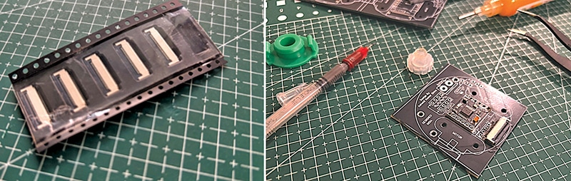
After assembly, the PCB forms a compact and fully integrated robot chassis that combines motor control, power distribution, and expansion interfaces on a single board. Fig. 4 shows the fabricated PCB and completed SMT assembly.
Construction and testing
After fabrication, the N20 geared motors were mounted in the designated slots, followed by soldering the DRV8833 motor driver, FPC connector, expansion headers, and other SMD components. The wheels were then attached to the motor shafts, completing the compact robot chassis assembly.
The motor driver is compatible with a wide range of microcontrollers and can be tested directly using the IndusBoard Coin. For testing, select the ESP32S2 Dev Module in the Arduino IDE, choose the appropriate COM port, and upload the program. The IndusBoard Coin is connected to the robot motor-driver PCB through an FPC cable, allowing the motors to operate according to the uploaded code. A source-code snippet is shown in Fig. 5.

Fig. 6 illustrates the construction and testing of the integrated motor-driver robot chassis. The image on the left shows the chassis connected to the controller through the FPC cable during operation, while the image on the right shows the fully assembled prototype with motors and wheels fitted.
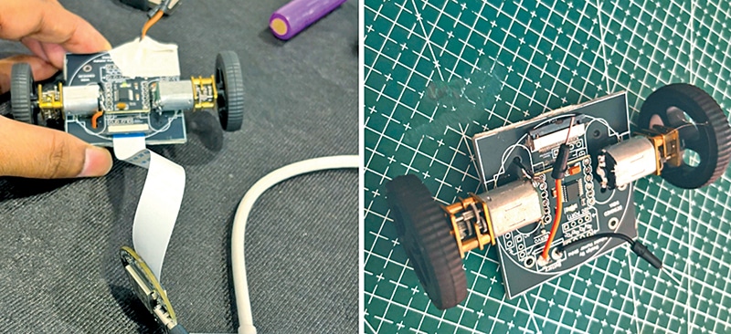
To verify performance, an ESP32-based controller was interfaced through the FPC connector and programmed to execute forward, reverse, left, and right movements. All functions operated successfully, confirming reliable communication through the FPC interface and proper operation of the DRV8833 motor driver. The tests also demonstrated the advantages of the integrated chassis design, including reduced wiring complexity and simplified assembly.
For future expansion, a dedicated microcontroller board with a compatible FPC connector can be designed according to the required I/O assignments. Alternatively, the IndusBoard Coin can be connected directly through the FPC cable to control motors, displays, sensors, and servo motors. If the FPC interface is not required, the motor driver can also be connected directly to a controller via the onboard header pins using the provided solder-jumper configuration.
Ashwini Kumar Sinha, an IoT and AI enthusiast, is Tech Journalist at EFY.