


 As the world gets hot due to global warming, air-conditioners are becoming a necessity to keep cool at home and workplaces. But at times it becomes difficult to provide proper drainage for the water condensed from air by the air-conditioners. It is not unusual, in absence of proper drainage, to collect the condensed water in buckets and throw it from time to time. This project aims to solve the problem.
The presented system can be installed in an air-conditioner’s water outlet, which should remain outside the air-conditioned room. The ultrasonic atomiser used here converts the condensed water collecting in the air-conditioner’s small tray into small aerosol particles using the mechanical energy produced by ultrasonic waves.
Circuit and working
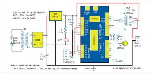
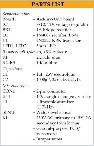
The circuit diagram of the condensed water atomiser is shown in Fig. 1. It is built around 15V step-down transformer X1, bridge rectifier BR1, 12V voltage regulator 7812 (IC1), Arduino Uno Board1, two 5mm LEDs—LED1 and LED2, 2N2222 transistor T1, 12V relay RL1, ultrasonic atomiser disk L1, and water-level sensor SEN18.

Arduino Uno
Arduino Uno board is connected to water-level sensor SEN18, which checks water level and gives signal to Arduino. The Arduino program compares the signal with the set value in program. If the water level is above the set value, relay RL1 is energised through Arduino pin 13 and the ultrasonic atomiser is turned on. The program turns off the ultrasonic atomiser by de-energising the relay when water level reaches below the set point.
Power supply
It provides power to the circuit and to the relay driver used for switching on the ultrasonic atomiser. It comprises 15V, 2A step-down transformer X1, bridge rectifier BR1, 1µF capacitor C1 and 1,000µF capacitor C2, 12V voltage regulator 7812, 2.2kΩ resistor R1, and power indicator LED1. Transformer X1 reduces the input 230V AC to 15V AC, which is converted to DC by BR1 and filtered by the capacitors to get a regulated 12V DC supply through IC 7812.

Water-level sensor SEN18
It has ten exposed conducting tracks of which five alternate one act as power tracks and the other five as sensing tracks. When the sensor is submerged vertically in water, all the tracks get bridged due to water’s conductivity and the sensor works as a mere resistor. The value of this resistor starts decreasing with decreasing water level. The sensor can be powered with a 3.3V or 5V DC power, depending on the available supply voltage.
Relay
It provides complete electrical isolation between the controlling circuit and the output circuit. Its contacts can handle a high current flow with total electrical isolation from delicate low-power electronic circuit. It is controlled/triggered by a low DC voltage. A 12V SPDT is used here to switch the solenoid valve on and off through an electrical pulse.
Ultrasonic atomiser
It has a piezoelectric transducer that converts high-frequency electronic signal to mechanical oscillations. The oscillations create small waves in the water that get converted to micro droplets, which break surface tension of the water body and become water vapour.
Software
Install Arduino IDE in your computer and upload program Ultrasonic_Atomizer.ino. In the program, Arduino digital pins 12 and 13 are defined as output and its analogue pin A0 is defined as input. Main functions of the Arduino code are explained below.
pinMode(). It configures the specified pin to behave either as an input or an output. See the description of digital pins for functionality of the pins. These can also be used as PWM pins.
digitalWrite(). If the pin has been configured as an output with pinMode(), its voltage will be set to the corresponding value: 5V (or 3.3V on 3.3V boards) for High, 0V (ground) for Low.
Serial. It is used for communication between the Arduino board and a computer or other devices. All Arduino boards have at least one serial port (also known as a UART, or USART), and some have several ports.
begin(). Sets the data rate in bits per second (baud) for serial data transmission. For communicating with the computer, use one of these rates: 300, 600, 1200, 2400, 4800, 9600, 14400, 19200, 28800, 38400, 57600, or 115200. You can, however, specify other rates, for example, to communicate over pins 0 and 1 with a component that requires a particular baud rate.
analogRead(). Reads the value from the specified analogue pin. Arduino board contains a multichannel, 10-bit analogue-to-digital converter. This means that it will map input voltages between 0 and the operating voltage (5V or 3.3V) into integer values between 0 and 1023.
println(). Prints data to the serial port as human-readable ASCII text followed by a carriage return character.
delay(). It is used to pause the program for the amount of time (in milliseconds) specified as parameter.
Construction and testing
Assemble the circuit on a general-purpose PCB or Veroboard as per Fig. 1. Connect 230V AC across the primary of transformer X1.
As shown in Fig. 1, signal ‘S’ pin of water-level sensor SEN18 is connected with analogue pin A0 of the Arduino Uno board and its ‘GND’ and ‘+’ pins are connected with ground and 5V pins, respectively. This water-level sensor will detect the water level available in the water container where the water from air-conditioner’s small tray is collected.
The SPDT relay RL1 used at the output side is triggered through resistor R3, pin 13 of Arduino Uno, switching transistor T1, along with diode D1 as flywheel diode. LED2 is connected as indicator LED with pin 12 of Arduino Uno with resistor R2 to indicate the activated/deactivated state of ultrasonic atomiser L1. The ultrasonic atomiser is connected as a load across normally-open (NO) terminal and common C terminal of relay RL1 with series connection of 12V DC power source.
There are a few things to be managed for this setup. The water level sensor is to be placed vertically in the container where the condensed water draining from the indoor unit will accumulate. And the ultrasonic atomiser disk is to be placed inside this container at its bottom.
After the setup, water level sensor should be calibrated according to the need. You can do it by following below-mentioned steps. First, upload Calibration.ino program in Arduino and then power on the system.
Step 1. Pour water into the water container and check the start level.
Step 2. Check the level on the serial monitor and note down the full and low-threshold levels. Here, 650 is the threshold level during testing.
After calibration, upload the Ultrasonic_Atomizer.ino code to Arduino board. After completing the whole setup, turn the power supply on. The water level sensor will detect the water level in the container.
When sensor detects full level of the water, Arduino will give high signal to the digital I/O pins 12 and 13 through the program. This will energise relay RL1. So, ultrasonic atomiser connected across the relay will get powered on and start atomising the water. Once water level reaches below the set level, it will automatically give low signal to digital output pin 13 of the Arduino through the program. This will de-energise relay RL1 and disconnect the power to ultrasonic atomiser L1, stopping atomising of the water.
This is how we can atomise the air-conditioner’s water and eliminate emptying of buckets full of water.
Download Source Code
Tej Vijaykumar Patel is vice president of Non Woven Division, SKAPS Industries India Pvt Ltd, Mundra. His interests include robotics, automation, and product development
Please note: If you are unable to download the source code, please try to open the page in incognito mode and retry or temporarily turn off the antivirus before downloading.

