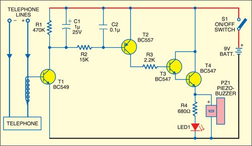
 This fully transistorised, simple circuit designed as a contactless telephone ringer provides an indication of incoming telephone call at a remote site like kitchen or bedroom in the building. It is implemented by winding five or more turns of a short hookup insulated wire around one of the wires of a twin telephone cable.

When your telephone rings, AC signal of about 60 Hz is generated in the telephone line. which causes fluctuating electric field arround telephone cable and develops a small induced voltage on the hookup cable. This induced voltage, when connected to the base of transistor T1, forward biases T1 and it conducts as ring is passing through the telephone cable. Consequently, transistors T2 through T4 also conduct. As a result, the piezobuzzer sounds and LED1 glows, which indicates that the telephone is ringing.
Assemble the circuit on a general-purpose PCB and wind an insulated electric cable around one of the telephone wires. You can also connect the buzzer and LED separately away from the telephone receiver’s room for audio and visual indication. Use a 9V battery to power the circuit.


