


 Motor starter reduces the load, torque and current surge of a motor during startup. On starting, the motor takes more than five times the normal running current. This overheats the motor’s armature winding and creates a sudden voltage dip in the power supply, which can be avoided by using a motor starter. There are many types of motor starters. Here we describe an electronic DC motor starter using Arduino Uno board. This circuit controls both soft-start and soft-stop timings through pulse-width modulation (PWM).
Circuit and working
Circuit diagram of the DC motor soft-starter is shown in Fig. 1. In addition to Arduino Uno board (Board1), it uses PIC817 optocoupler (IC1), p-channel IRF9530 MOSFET (T1), 1N4007 rectifier diode (D1), 12V DC motor (M1) for testing, bi-colour LED (LED1) and a few other components.
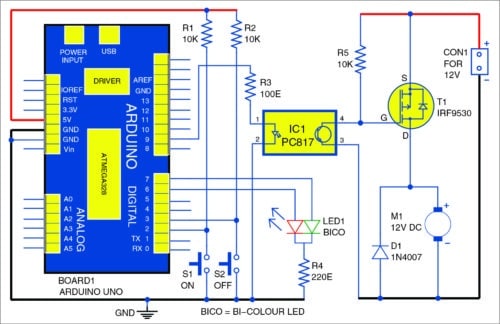

Fig. 1: Circuit diagram of DC motor starter using Arduino Uno
Arduino Uno board is an important part of the circuit that generates PWM signals. Pushbuttons (S1 and S2) are used to soft-start and soft-stop the motor. The bi-colour LED indicates whether the motor is in soft-start or soft-stop mode.
Soft-start
When the circuit is switched on, the motor is at rest and LED1 off. When push button S1 is pressed momentarily, the voltage across the motor increases gradually and attains maximum voltage after the predetermined soft-start timing. So the motor first starts at a slow speed. In this state, LED1 emits green light. After the soft-start time, i.e., in running condition, LED1 emits orange light, indicating that the motor is running at the rated speed.
Soft-stop
If pushbutton S2 is pressed momentarily while the motor is running at the rated speed, the voltage across the motor decreases gradually and becomes zero after the soft-stop time. So the motor speed also decreases gradually and it finally stops after the soft-stop time. In this state, LED1 emits red colour. After the soft-stop time, LED1 doesn’t glow, indicating that the motor is at rest.
Arduino Uno is programmed such that if switch S1 or S2 is pressed more than once before the timing ends, it executes only once. This prevents the motor from restarting suddenly.
The circuit is isolated by an optocoupler (IC1) so that any disturbance in the motor power supply doesn’t affect the Arduino Uno board. The freewheeling diode (D1) gives additional protection over induced voltage when the motor is turned off.
The circuit’s operation is controlled using the software program loaded into the internal memory of Arduino Uno board. The program (softs.ino) is written in Arduino programming language sketch. Arduino IDE is used to compile and upload the program to the Arduino board.

Construction and testing
A PCB layout of the DC motor soft-starter is shown in Fig. 2 and its components layout in Fig. 3. After assembling the circuit on a PCB, connect CON2 to Arduino Uno board through external male-to-male jumper wires. After uploading the code to Board1, enclose the assembled PCB along with Board1 in a suitable plastic box.
The circuit works off the 5V USB power supply used for Arduino Uno board. Regulated 12V power supply is used to operate the DC motor.
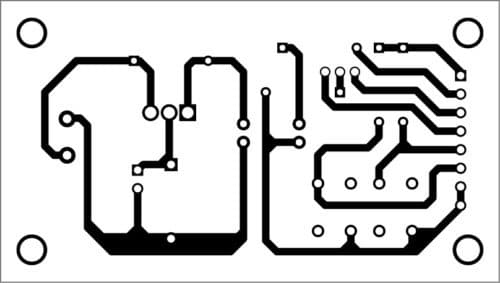
Fig. 2: PCB layout of the DC motor starter using Arduino Uno
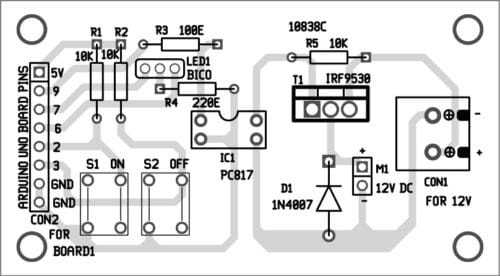
Fig. 3: Components layout for the PCB
Download PCB and component layout PDFs: click here
Further application
The circuit can be converted into an AC motor soft-starter by using thyristors in place of MOSFET T1. It can be used along with device control projects. Additional protection and closed-loop control can be included, if required. Different timings and PWM values can be set for both soft-start and soft-stop.
Download source code
Hi there!
https://www.electronicsforu.com/electronics-projects/dc-motor-starter-using-arduino-uno-board
Im going to build this circuit.
is this possible to get the source code?
i tryed to click this source code link, but failed!
Palj
The source code is already given at the end of the project.
Where it’s not working
No it isn’t working. Pity I am dead keen on this !
Hello,
I need to build this project but I want one more function on it.
I need with a potentiometer to preselect the max PWM value and when hit the start button gradually reach that preselect max value.
Any idea for that?
Thank you
Here’s the reply from author A. Samiuddhin: “Thank you for giving interest in my article. Let us assume the potentiometer wiper is connected to analog input A0, 5V and ground on both ends of the potentiometer. Replace the pwm values with a variable to store the analog input A0 value. Change the maximum and minimum value on the “for” loop on both “on()” and “off” function.
Simply follow the below steps:
1. Replace the int soft[] = {0,25,50,75,100,125,150,175,200,225}; line with a variable as unsigned int,
to store the A0 value. (Here I mention the variable as maxPWM)
2. In the void loop function, add the below two lines.
maxPWM = analogRead(A0);
maxPWM /= 4;
3. Change the for loop as indicated below on both on() and off() function
for (n=0; n0; m–) in off() function,”
The first line in the code says that motor is connected to pin no 9. The motor is not connected to pin no 9. Please Clarify.
The first line on the code says that motor is connected to pin no 9. Its not the case please clarify
please give the source code of this project
or coding of ardino uno
The source code is present at the end of the article.
Plz send me coding of ardino
“I established Stepdown transformer to design own power supply to led lights design
I used Stepdown 12 volts tarnsformer and lm317 100 l variable resistor I connected the lights from transformer and other side I connected Arduino Uno with 5 volts charger but the program is executed in l board but other transformer side light was not blinking my doubt is both grounds are commonly not connected is that problem I feared about short circuit please give any answer how to turn on power supply thank you.”