Need to connect more than one audio-video (AV) source to your colour television? Don’t worry, here’s an AV input expander for your TV. It is inexpensive and easy to construct.
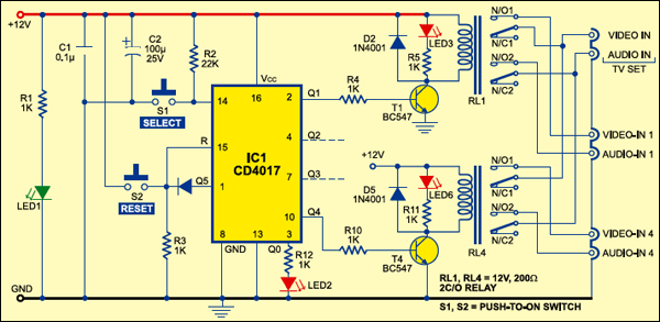
The working of the circuit is simple and straightforward. Whenever 12V DC is applied to the circuit, power-on LED1 glows. Now reset the decade counter by momentarily pressing switch S2 to make Q0 output of IC1 high. LED2 glows to indicate that the circuit is ready to work.Switch S1 is used for selecting a particular audio-video (AV) signal. To select the first AV signal, press switch S1 once. To select the second AV signal, press switch S1 twice. In the same way, you can select the other two signals.
Momentarily pressing of switch S1 once results in clocking of the decade counter and relay driver transistor T1 conducts to energise relay RL1. Now normally opened (N/O) contacts of two-changeover relay RL1 connect the television set’s inputs to the first AV signal (marked as Video-In 1 and Audio-in 1). LED3 glows to indicate this.
When you press switch S1 twice, the Q2 output of IC1 goes high. Consequently, 2C/O relay RL2 (not shown in the circuit) energises and television inputs are connected to the second AV signal (not shown in the figure). LED4 (not shown in figure) glows to indicate this.
Similarly, pressing switch S1 thrice makes the Q3 output of IC1 high. Consequently, 2C/O relay RL3 (not shown in the figure) energises and the television inputs are connected to the third AV signal source. LED5 (not shown in the figure) glows to indicate this. Again, pressing switch S1 four times makes the Q4 output of IC1 high. Consequently, 2C/O relay RL4 energises and the TV inputs are connected to the fourth AV signal source (marked as Video-in 4 and Audio-in 4). LED6 glows to indicate this.
Further pressing of switch S1 resets the decade counter and LED2 glows again. Thereafter, the cycle repeats. The circuit is wired for four-input selection, therefore the Q5 output of IC1 is connected to reset pin 15 of IC1.
Enclose the assembled PCB along with the relays in a cabinet with the input/output sockets and indicators mounted on the body of the cabinet.