


 This article describes the implementation of a digital frequency meter using Arduino Uno to determine the sinusoidal frequency signal in the range of 20Hz to 5kHz. The logic involves counting the total number of pulses per second that appear at a digital pin of Arduino.
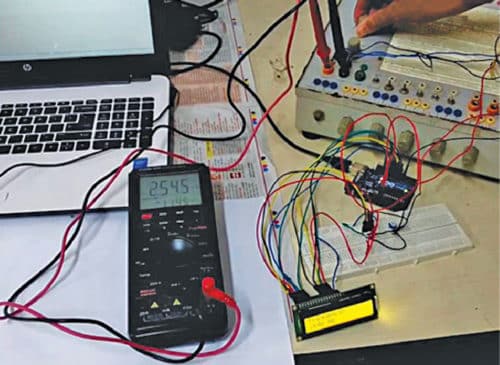
The authors’ prototype is shown in Fig. 1.
Block diagram of the digital frequency meter is shown in Fig. 2.


Circuit and working
The circuit diagram of the digital frequency meter is shown in Fig. 3. It consists of Arduino Uno board, optocoupler MCT2E (IC1), 16×2 LCD and a few other components. The sinusoidal signal whose frequency is to be measured is applied to signal input terminals (CON1), as shown in Fig. 3. In this frequency meter, the test signal must be an alternating one and its amplitude must not exceed the maximum forward diode current rating of the optocoupler for a particular value of series resistance. (Here, we used 1k series resistance.)
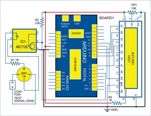
The next stage is a bridge rectifier, which converts the alternating signal to fully-rectified pulsating DC signal. This fully-rectified pulsating DC signal is applied to the diode side of the optocoupler. With the help of the optocoupler, spikes are produced. Frequency of the spikes is twice that of test signal input. These spikes are applied to digital I/O pin 5 of Arduino, and the program running in the CPU of the microcontroller (MCU) calculates the frequency of the test signal and displays it on the 16×2 LCD and on the serial monitor of the PC.
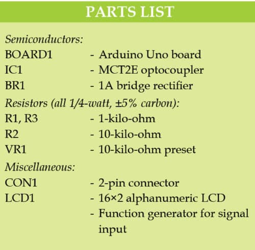
Major components used in this project are:
Arduino Uno
Arduino Uno is an AVR ATmega328P MCU-based development board with six analogue input pins and 14 digital I/O pins. The MCU has 32kB ISP flash memory, 2kB RAM and 1kB EEPROM. The board provides the capability of serial communication via UART, SPI and I2C. The MCU can operate at a clock frequency of 16MHz. In this project, digital I/O pin 5 has been used as pulse input pin, and digital I/O pins 7, 8, 9, 10, 11 and 12 of Arduino Uno board are used to interface with the LCD.
Bridge rectifier
The bridge rectifier (BR1) is used to rectify the alternating input signal to pulsating DC.
Optocoupler
The optocoupler is used to produce spikes from the pulsating DC waveform.
16×2 LCD
The 16×2 LCD is used to display the frequency. It consists of 16 columns and two rows for displaying data. The LCD used here is a backlit one. It is interfaced with Arduino in 4-bit mode. LCD pins RS, EN, D4, D5, D6 and D7 are connected to digital I/O pins 12, 11, 7, 8, 9 and 10 of Arduino, respectively.
Software
Arduino IDE is used for programming Arduino Uno. Open the source code/sketch (Freq_meter_1.ino), and select the COM port and board from Tools menu in Arduino IDE. After selecting the correct COM port and board, upload the source code to the board.
Download source folder here: click here
Construction and testing
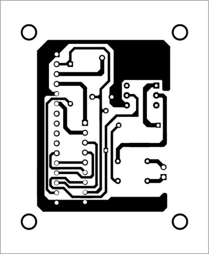
The PCB layout of the digital frequency meter is shown in Fig. 4 and its components layout in Fig. 5.
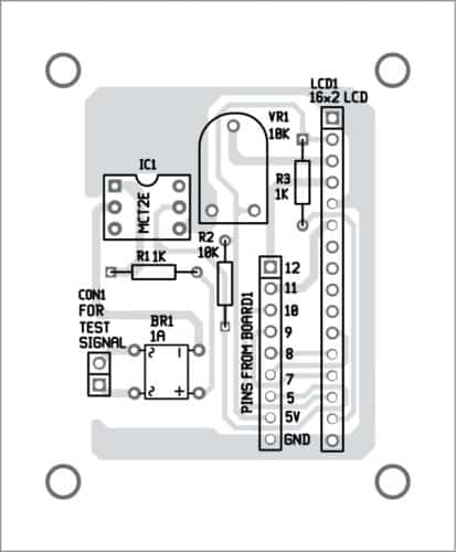
Download PCB and Component Layout PDFs: click here
Assemble the components on the PCB, as per the circuit diagram. After this, connect the USB cable to Arduino and give the test signal at CON1 and check the frequency on LCD1 and the serial monitor of Arduino.
Shibendu Mahata is M.Tech (gold medallist) in instrumentation and electronics engineering from Jadavpur University. He is interested in designing MCU-based real-time embedded signal processing and process control systems.
Saikat Patra is passionate about electronics and MCU-based embedded system applications.


plz draw ina vhf video calling circuit