
This light cum room freshener module offers two choices. In the first choice, the room freshener spray and a small LED light get activated for three to five seconds.
In the second choice, where a switch is employed, the spray stops (after three to five seconds), but the LED continues to glow. The second choice can double up as a night bedside lamp cum room freshener with your favorite choice of scent.
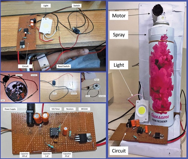
Fig. 1 shows the authors’ prototype of the entire setup. Fig. 2 shows the block diagram of the device.

POC Video Tutorial in English
POC Video Tutorial in Hindi
The components used to build this module are listed in the Bill of Materials table.
| Bill of Materials | ||
| Components | Quantity | Description |
| NE555 timer (IC1) | 1 | IC that controls the on/off signals |
| IRLZ44N/IRFZ44 (T1) | 1 | Power MOSFET to drive motor |
| Capacitors (C1-C4) | 4 | For timing and ripple removing |
| Resistors (R1-R3) | 3 | For biasing |
| Modified motor (M1) | 1 | To activate the room freshener |
| Switch SPDT (S2) | 1 | To on and off the circuit |
| Reed switch (S1) | 1 | To power on or off using magnet |
| 12V LED (LED1) | 1 | To light up |
| 12V DC adaptor | 1 | To power up the circuit |
The motor used in the proposed setup is modified. The gear combination found in Home Miller’s 250V motor is applied to a 4000RPM, 12V DC motor, and one round-end effector is attached.
The purpose is to activate the room freshener during one full rotation of the motor. Torque is the main reason for choosing the Miller’s motor gear combination.

The popular NE555 timer IC used in the circuit consists of comparators, flip-flops, resistors, and transistors, all integrated onto a single chip. It is available in different packages, including DIP (dual in-line package) and surface mount versions, making it easy to use in various circuit designs.
Additionally, IRLZ44N, a specific model of a power MOSFET (metal-oxide-semiconductor field-effect transistor) commonly used in electronic circuits for switching applications, is employed. It is commonly used where high power switching is required, such as motor control, power supplies, inverters, and amplifiers.
A reed switch, also known as a reed contact, is used as a secondary switch. It is an electrical switch that operates based on the magnetic field. It has two ferromagnetic reed blades enclosed in a glass tube filled with an inert gas.
When no magnetic field is present, the reed blades remain separated, and the switch is in an open state, which means it does not conduct electric current. However, when a magnetic field is applied (in the present case using a fridge magnet) near the reed switch, the magnetic force causes the reed blades to attract and touch each other, closing the switch and allowing electric current to flow.
Room Freshener Machine – Circuit and Working
Fig. 3 shows the circuit diagram of the two-way operated light cum room freshener module. It comprises a NE555 timer, MOSFET IRLZ44N (T1), reed switch (S1), SPDT switch (S2), DC motor (M1), and a few other components.
Upon activating either of the switching techniques, the room freshener gets dispensed once, coinciding with a single rotation of the motor. Let’s examine the step-by-step process.
The motor is interfaced with the power supply using a MOSFET and an NE555 timer IC. The switch (S2) and reed switch (S1) are connected in parallel so that either of them in a high state will activate the circuit, as one common terminal of the switches (in parallel) is linked to the negative terminal of the power supply and the other is grounded.

With an RC network consisting of resistor R3 (47k) and capacitor C2 (10µF), a trigger is generated at pin 2 of the NE555 timer IC.
Also Check: Capacitance Conversion Calculator
Pin 5 (control voltage) through capacitor C1 (1nF) is grounded. Pin 1 (ground) of the IC 555 is also connected to the ground.
Also Check: Resistor Color Code Calculator
Pin 4 (reset) and pin 8 (VCC) of IC 555 are both connected to the positive of the supply.
Pin 6 (threshold) and pin 7 (discharge) of IC 555 are both connected to resistor R1 (10k) and capacitor C3 (200µF), deciding the duration of the monopulse generated (given by T=1.1 x R1 x C3) as the IC 555 works in the monostable mode of operation.
The pin 3 (output) of the NE555 timer IC is connected to the gate of MOSFET IRLZ44N via resistor R2 (10k).
The source pin of IRLZ44N is connected to the ground, and its drain pin is connected to the negative terminal of motor M1.
The positive of the motor is connected to the positive of the supply. The motor has a capacitor C4 (100µF) wired across it to reduce radio frequency EMI caused by arcing between the brushes and the commutator.
Upon activating either of the switching techniques, the room freshener is dispensed and the light switches on.
Light Cum Room Freshener – Testing
Assemble the module on a general-purpose PCB/breadboard as per the circuit diagram. It would be helpful to refer to the author’s prototype shown in Fig. 1 before assembling. After proper assembly, the module is ready to use.
For testing, bring a magnet near the reed switch (S1). When the circuit is enabled, a spray and the light would be initiated for a few seconds. In the second choice, where a switch (S2) is employed, the spray stops after a few seconds, but the light continues to glow.
The LED1 light is integrated into the system to indicate the circuit’s state and to provide a source of light in case the system is kept in darkness. In conclusion, the module can prove a wonderful, personalized, low-cost alternative to the existing choices available in the market.
Dr Geetali Saha is a faculty member of the Department of Electronics and Communication Engineering, GCET, Anand, Gujarat, and Dhruv Vachhani from the 3rd Year IoT Engineering Department has successfully implemented this device