


History of DC Motor
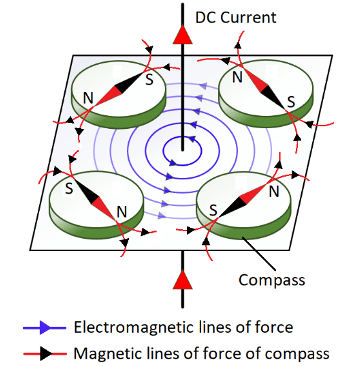
People or scientists in the earlier nineteenth century used to think electricity and magnetism as two different topics until the electromagnetism was invented. In 1820, Hans Christian Oersted noticed that a compass (magnetic needle) was deflected when placed nearby a wire with a current flowing through it. As seen in Fig.1, dc current flows through the wire in the marked direction which generates an electromagnetic field (anticlockwise) around the wire. This electromagnetic field interacts with the compass’s magnetic field resulting in deflection of the compass needles placed in four different places. This was the very first demonstration of a mechanical movement caused by an electric current. Taking this concept a step forward, just a year later, the great scientific thinker Michael Faraday figured out how to turn it into motion thus creating the world’s first dc motor. Though a primitive device that served no practical purpose, it was a great leap for humankind and led to the much more sophisticated motors of today.
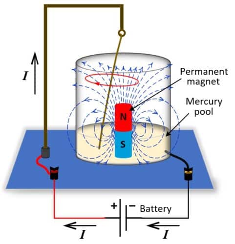
Faraday’s first created experiment setup comprised of a metal wire, suspended in a cup of mercury which is a good conductor of electricity. The wire was arranged so that one end hung free in contact with the mercury bath able to move freely. A permanent magnet was placed in the mercury bath protruding up from the bottom-center of the cup. When current from an electric battery ran through the wire to the mercury bath (current direction from positive to negative is marked by arrows in Fig. 2), it produced a circular magnetic field around the wire (the phenomenon discovered by Oersted). The wire’s electromagnetic field interacted with the magnetic field of the permanent magnet, causing a clockwise rotation of the wire around the magnet.
Working principle and construction of a DC Motor
The working principle of a DC motor is based on the fact that when a current-carrying conductor is placed in a magnetic field, the conductor experiences a mechanical force. The direction and magnitude of this force is given by Fleming’s left-hand rule, F-> = B->I->L. Where, F-> represents the force, B-> is the magnetic flux density, I-> be the current and L be the length of the wire. The direction of this force is perpendicular to both the directions of the current flowing through the wire and the external magnetic field. This experienced force produces the torque which turns the DC motor.
DC motor is majorly comprised of two parts, Stator (static part: permanent magnet) and Rotor (rotating part: armature winding). The armature is placed in the magnetic field produced by the north and south poles of a permanent magnet as shown in Fig.3(a),(b).
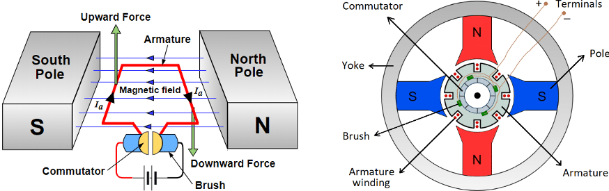
When a DC supply is connected the armature winding, an electric current sets up in the armature conductors which experience a force (in the direction marked by arrows) due to the magnetic field, according to the principle stated before. One side of armature conductor under North-pole carries current in one direction whereas the other side under South-pole carries current in the opposite direction and hence force on each side will act opposite to each other. Therefore, if one side of the armature moves in upward direction, the other side will move in the downward direction which results in a driving torque rotating the armature in clockwise direction. When the conductor moves from one side of a brush to the other, the current in that conductor is reversed. At the same time, it comes under the influence of the next pole which is of opposite polarity. Consequently, the direction of the force on the conductor remains unchanged. It should be noted that the commutator reverses the current in each conductor as it passes from one pole to another which helps to develop a continuous and unidirectional torque in order to keep rotating the rotor. Otherwise, the direction of the force would have reversed every time when the conductor comes under the influence of opposite magnetic pole.
When the armature of a dc motor rotates, the conductors also cut the magnetic flux lines and hence an emf induces in the armature winding according to the Faraday’s law of electromagnetic induction. The direction of this induced emf is such that it opposes the armature current and hence called back-emf.
Dynamic modelling of DC motor
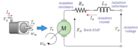
The complete dynamic model of a DC motor drive system can be represented with the following four equations: armature circuit, back-electromotive force (back-emf), torque and mechanical load system. The voltage equation for the armature winding of a DC motor is given by;
Va (t)=RaIa(t)+La((dla(t))/dt)+Ea(t) —–(1)
Where, Ia(t) represents the armature current, Lais armature winding inductance, Ra is the armature winding resistance, and Ea(t) is the back-emf induced by the rotation of the armature winding in the magnetic field. The back-emf voltage Ea(t) is proportional to the angular velocity ωm(t) of the rotor, can be expressed as;
Ea(t)=kbωm(t) —–(2)
Where, kb is the back-emf constant. Additionally, the motor generates a torque Te(t) proportional to the armature current, given as;
Te(t)=kTIa(t) —–(3)
Where, kT is the torque constant. When a DC motor with the output torque in Eq. (3) is driving a mechanical load system, the rotor speed can be determined from the equation of motion;
Te(t)=Jm(dωm(t))/dt+Bmωm(t)+TL(t) —–(4)
Where, TL(t) is the load torque, Jm is the moment inertia and Bm is the friction coefficient of the DC motor drive system respectively.
The equation 4 is not written correctly and creates confusion. The technological articles should be simple and clear and should not give any wring information under any circumstances.