Most microphones’ output signals are weak and cannot be directly connected to some other circuits. Also, some microphones require DC power supply or high impedance inputs. Here is a dual (stereo) preamplifier for microphones that can be used with a wide variety of circuits, including analogue-to-digital converters (ADC), microcontroller (MCU) kits and single-board computers such as Arduino.
Circuit and working
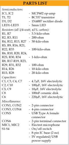
The circuit diagram of a dual microphone preamplifier is shown in Fig. 1. It is built around two electret microphones (MIC1 and MIC2), two low-voltage MCP602 operational amplifiers (IC1 and IC2), three LEDs (LED1 through LED3), two BC337 transistors (T1 and T2), two 1N4007 diodes (D1 and D2), and a few other components.

The circuit has two independent channels. The first audio channel comprises MIC1, IC1, and T1, and the second channel comprises MIC2, IC2, and T2. CON1 and CON2 are connectors for MIC1 and MIC2, respectively.

Switches S1 and S2 are closed only if microphones need an external power supply. If small loudspeakers or headphones are used as microphones, these switches should be opened because these devices produce a much lower signal when used as dynamic microphones.
IC1 and IC2 work as non-inverting amplifiers with a gain of 31 each. When switches S3 and S4 are opened, the gain is 31, and when these are closed, the gain is 11. The gain is selected according to the microphones, power supply, and required output levels.
First and second channel outputs are available across connectors CON3 and CON4, respectively. Preamplifier channels have six outputs—OUT1 through OUT6. While four outputs (OUT2, OUT3, OUT5, and OUT6) have DC components of around Vcc/2, two outputs (OUT1 and OUT4) do not have DC components. All outputs have series protecting resistors.
DC power supply (2.7V-5.5V) can be applied to connector CON6 or 5V supply on the USB connector CON5. Resistors R30 and R34, capacitor C10, and diode D2 produce half of the power supply needed for biasing the op-amp. Diode D1 and fuse F1 protect the circuit from reverse polarity connection of the power supply.
Each audio channel has a buffer driving an LED to indicate the level of the output signal. LED1 and LED3 should be of low forward drop voltage—about 1.6V or below with low forward current. T1 and T2 drive LED1 and LED3, respectively.
Construction and testing
An actual-size PCB layout for dual microphone preamplifier is shown in Fig. 2 and its components layout in Fig. 3. After assembling the circuit on the PCB, connect a 5V USB power supply across CON5. The glowing of LED2 indicates the presence of power in the circuit. The outputs (CON3 and CON4) can be directly connected to an ADC, MCU kit, or Arduino.
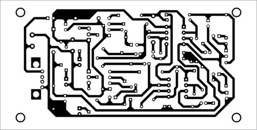
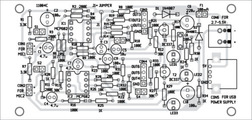
Download PCB and Component Layout PDFs: click here
The circuit does not need any adjustment to work properly. If required, the gain of the preamplifier can be optimised for particular microphones or required output levels of the signals.
Petre Tzv Petrov was a researcher and assistant professor at the Technical University of Sofia, Bulgaria, and expert lecturer in OFPPT (Casablanca), Kingdom of Morocco. Currently, he is working as an electronics engineer in the private sector in Bulgaria