


An operational amplifier or op-amp is simply a linear Integrated Circuit (IC) having multiple-terminals. The op-amp can be considered to be a voltage amplifying device that is designed to be used with external feedback components such as resistors and capacitors between its output and input terminals. It is a high-gain electronic voltage amplifier with a differential input and usually a single-ended output.

Op-amps are among the most widely used electronic devices today as they are used in a vast array of consumer, industrial and scientific devices.

Op-amp Table of Contents
Brief History
- In 1947, the first operational amplifier developed from vaccum tubes by John R. Ragazzini of Columbia University.
- With the development of silicon-based transistor, the concept of ICs became a reality. In the early 1960s, Robert J. Wildar of Fairchild Semiconductor fabricated opamp, the μA702.
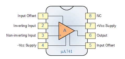
- In 1968, the μA741 was released, leading it to wide production.
Modern day op-amps are available in:
- The metal can package (TO) with 8 pins
- The dual-in line package (DIP) with 8/14 pins
- The flat package of flat pack with 10/14 pins
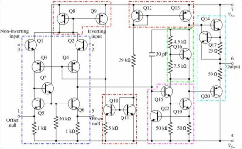
Op-amp Circuit Construction
The inner schematic of a typical operational amplifier looks like this:
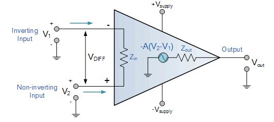
The op-amp typically has five terminals. They are listed in the following order:
- Vs+: Positive Power Supply
- Vs-: Negative Power Supply
- V+: Non-Inverting Input
- V-: Inverting Input and
- Vout: Output
The terminal with a (-) sign is called inverting input terminal and the terminal with (+) sign is called non-inverting input terminal.
The V+ and V− power supply terminals are connected to the positive and negative terminals of a DC voltage source respectively. The common terminal of the V+ and V− is connected to a reference point or ground, else twice the supply voltage may damage the op-amp.
Types of Op-Amps
An op-amp has countless applications and forms the basic building block of linear and non-linear analogue systems. Some of the types of operational amplifier include:
- A differential amplifier, which is a circuit that amplifies the difference between two signals.
- The instrumentation amplifier, which is usually built from three op-amps and helps amplify the output of a transducer (consisting of measured physical quantities).
- The isolation amplifier, which is like an instrumentation amplifier, but having tolerance to common-mode voltages (that destroy an ordinary op-amp).
- A negative-feedback amplifier, which is usually built from one or more op-amps and a resistive feedback network.
- Power amplifiers to amplify small signals received from an input source such as microphone or antenna.
Op-amp Parameter and Idealised Characteristic
Open Loop Gain (Avo): Ideally, the op-amp amplifies signals to the maximum extent possible. Practically, the open-loop gain varies from 20,000 to 200,000 when feedback is not used.
Input Impedance (Zin): Ideally infinite to avoid allowing current to enter the input. Actual operational amplifiers display minimal input leakage currents ranging from picoseconds to milliamperes.
Output Impedance (Zout): Ideally, zero offset voltage enables the op-amp to provide the load with full voltage. The actual output impedance varies between 100Ω and 20kΩ, restricting the voltage that can be supplied to the load.
Bandwidth (BW): Ideally infinite, which enables signal amplification at any frequency. Gain at higher frequencies is reduced by the limited bandwidth of real op-amps, which is specified by the gain-bandwidth product.
Offset Voltage (Vio): Zero is the ideal result, which occurs when both inputs are equal. In practical terms, even with equal inputs, there is a minor offset voltage that results in a modest output.
Operational Amplifier Configurations
Two primary configurations for operational amplifiers, or op-amps, are open-loop and closed-loop. The op-amp amplifies and processes the input signal in accordance with these arrangements.
Open-Loop Configuration:
There is no feedback between the input and the output in an open-loop setup. At its highest gain, the op-amp functions at a very high level (usually in the region of 100,000 or more).

However, this results in a very sensitive amplifier that frequently experiences output saturation. Because they lack stability and control, open-loop systems are typically impractical for linear applications.
Key Features:
- Maximum gain.
- No feedback is used.
- Suitable for comparator applications where the output toggles between high and low states.
Closed-Loop Configuration:
In a closed-loop system, some of the output is returned back into the system as positive or negative feedback (negative feedback is most prevalent). An op-amp with regulated output will behave predictably due to negative feedback, which aids in gain stabilization and control.

There are two types of closed-loop configurations:
- Inverting Configuration: The non-inverting terminal is grounded, and the input signal is connected to the inverting terminal. With a 180-degree phase shift from the input, the output is inverted.
- Non-Inverting Configuration: The non-inverting terminal receives the input signal. The output is regulated amplification of the input signal.
Key Features:
- Controlled and stable gain.
- Negative feedback improves linearity and reduces distortion.
- Commonly used in amplifiers, filters, and other signal processing circuits.
Real vs Ideal Op-amp
|
Parameter |
Ideal op-amp |
Real op-amp |
|
Voltage Gain |
∞ (Infinity) |
10,000 to 100,000 |
|
Input Impedance |
∞ (Infinity) |
Very high (in the range of megaohms) |
|
Output Impedance |
0 (Zero) |
Low but not zero |
|
Bandwidth |
∞ (Infinity) |
Limited (dependent on gain-bandwidth product) |
|
Power Consumption |
0 (Zero) |
Depends on the specific op-amp model |

Op-Amp Classification

Dual Supply Op-Amp: The power supplies used by a Dual Supply Op-Amp are positive and negative, respectively represented by the symbols +Vcc and -Vcc. This arrangement, which is frequently utilized in conventional analog applications, enables the output to change both positively and negatively, enabling the amplification of both positive and negative input signals.

Single Supply Op-Amp: The ground (0V) acts as the reference point for a single supply operational amplifier, which uses a single positive power supply, usually represented as +Vcc. In battery-operated, low-power devices or scenarios with a single power source, this design is frequently utilized. To function within the power supply’s voltage range, this kind of op-amp requires biasing both the input and output signals.

Rail-to-Rail Op-Amp: In order to optimize input and output voltage fluctuation and enable the output to go next to the ground and positive power supply rails, a rail-to-rail operational amplifier (Op-Amp) is constructed. Because of this capability, these op-amps can fully utilize the supply voltage, which makes them perfect for high-precision, low-voltage applications.
Op-Amp Operation
Ideally, an op-amp amplifies only the difference in voltage between the two, also called differential input voltage. The output voltage of the op-amp Vout is given by the equation:
Vout = AOL (V+ – V–)
where AOL is the open-loop gain of the amplifier.
In a linear operational amplifier, the output signal is the amplification factor, known as the amplifier’s gain (A) multiplied by the value of the input signal.
Some other important electrical parameters to consider are:
- Input offset voltage: It is the voltage that must be applied between the input terminals of an op-amp to nullify the output.
- Input offset current: It is the algebraic difference between the currents into the (-) input and (+) input.
- Input bias current: It is the average of the currents entering into the (-) input and (+) input terminals of an op-amp.
- Input resistance: It is the differential input resistance as seen at either of the input terminals with the other terminal connected to ground.
- Input capacitance: It is the equivalent capacitance that can be measured at either of the input terminal with the other terminal connected to ground.
- Slew rate: It is defined as the maximum rate of change of output voltage caused by a step input voltage. The slew rate improves with higher closed loop gain and DC supply voltage. It is also a function to temperature and generally decreases with an increase in temperature.
Note: Although an ideal op-amp draws no current from the source and its response is independent of temperature, a real op-amp does not work this way.
An op-amp only responds to the difference between the two voltages irrespective of the individual values at the inputs.
External resistors or capacitors are often connected to the op-amp in many ways to form basic circuits including Inverting, Non-Inverting, Voltage Follower, Summing, Differential, Integrator and Differentiator type amplifiers. An op-amp is easily available in IC packaging, the most common being the μA-741.
Operational Modes of Op-Amps
An operational amplifier, or Op-Amp, is a direct-coupled, high-gain amplifier used for integration, subtraction, and summation. This basic analog integrated circuit (IC) functions in several modes according to its intended function. These modes are explained below:
Single-Ended Operation: In order to apply the signal to the other input, one input in this mode is linked to ground. Terminal 4’s output is inverted while terminal 3’s output remains unchanged if the signal is sent to terminal 1. The output of terminal 4 is inverted if the signal is sent to terminal 2, but the output of terminal 3 remains unchanged.

Differential Operation: Both inputs get two opposed signals that are applied out of phase. By twice the signal compared to the single-ended mode, the output is stronger. A different term for this is a double-ended procedure.

Common Mode Operation: The output signals cancel each other out when the same in-phase signals are applied to both inputs, producing zero output.

Inverting and Non-inverting Inputs: Terminal 1 is the non-inverting input since a positive input result in a non-inverted output. On the other hand, terminal 2 is designated as the inverting input when positive input is applied, resulting in an inverted output.
Advantages of Op-Amps
- High Gain: Op-amps are useful for amplifying weak signals because of their high voltage gain.
- Versatile Applications: Numerous configurations are possible for them, including voltage regulation, amplification, filtering, integration, and distinction.
- Single Supply Operation: The ability of many op-amps to run off of a single power supply makes circuit design simpler.
- Cost-Effective: Op-amps are widely available and reasonably priced, which makes them a cost-effective option for a variety of applications.
- High Input Impedance: Op-amps minimize loading effects on the previous circuit by drawing relatively little current from the input signal.
Disadvantages of Op-Amps
- Limited Output Current: In power applications, the majority of op-amps may not be able to generate high output currents.
- Finite Gain and Bandwidth: Op-amps have a high gain, but it is finite, and they have a finite bandwidth. Performance in high-frequency applications may be impacted by this.
- Saturation: The output will saturate and produce distortion if the input is higher than the supply voltage.
- Temperature Dependence: Temperature variations can have an impact on performance, which can alter precision and stability.
- Noise: They may cause the signal to become noisy, which could be problematic in delicate applications.
Operational Amplifier Applications
An op-amp has countless applications and forms the basic building block of linear and non-linear analogue systems.
In linear circuits, the output signal varies with the input signal in a linear manner. Some of the linear applications are:
- Adder
- Subtractor
- Voltage to Current Converter (Transconductance Amplifier)
- Current to Voltage Converter (Transresistance Amplifier)
- Instrumentation amplifier
- Power amplifier
Another class of circuits with highly non-linear input to output characteristics are:
- Rectifier
- Peak detector
- Clipper
- Clamper
- Sample and hold circuit
- Log and antilog amplifier
- Multiplier and divider
- Comparator
Thanks to op-amps and associated circuits, they have become an integral part of audio amplifiers, waveform generators, voltage regulators, active filters, 555 timers, A-D and D-A converters.
FAQs about Op-Amps
What is an operational amplifier?
- An operational amplifier is a high-gain voltage amplifier with differential inputs and usually a single-ended output, used in various electronic applications.
Can op-amps be used in oscillators?
- Yes, op-amps can be used in various oscillator circuits, such as triangle wave, sine wave, and square wave oscillators.
What is the difference between an op-amp and a comparator?
- An op-amp amplifies the difference between its inputs, while a comparator compares two voltages and outputs a digital signal indicating which is higher.
How do I choose an op-amp for my application?
- Consider factors such as voltage range, bandwidth, input/output impedance, power consumption, and noise specifications.
What is feedback in op-amp circuits?
- Feedback is a process where a portion of the output is fed back to the input. Negative feedback stabilizes gain and improves linearity, while positive feedback can lead to oscillation.
Can op-amps be used for digital circuits?
- Op-amps are primarily analog devices but can be used in analog-to-digital converters (ADCs) and other analog interfacing applications.
Very informative.Reading your articles on various topics leads to refresh the fundas.
Thank you for your valuable feedback.
Totally UN- helpful !!!!!!!!!
nope
Good work mam
Really helpfull, gain should not have units though.
this gives a clarity for me
Thank you very much, Helpful.
You are most welcome.
v.helpful and concise summary…
Thank You for your feedback.
Why opamp has two inputs?
Basically OP AMPs are differential amplifier. So you have + and – inputs.
sir for comparator which opamp is used
LM339 or LM393 works for unipolar inputs. For bipolar you may need LM311, LF311 or LM319 etc.
Please check with datasheet for specifications, applications and ratings.
what controls the bias of an OP amp?