


Presented here is a simple circuit that can drive two motors for a small robot, allowing the robot to negotiate an obstacle course. Two light-dependent resistors (LDRs) are used to detect the obstacle and the motors are driven correspondingly to avoid the obstacles automatically. Two H-bridge motor circuits are used that can drive each motor forward or backward, or stop it, independently.
Circuit and working
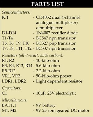
Fig. 1 shows the circuit of dual motor control. The circuit is built around four-channel multiplexer CD4052 (IC1), light-dependent resistors (LDR1 and LDR2), four BC547 npn transistors (T1 through T4), four BC338 transistors (T7, T8, T11 and T12), four BC327 pnp transistors (T5, T6, T9 and T10) and a few other components.
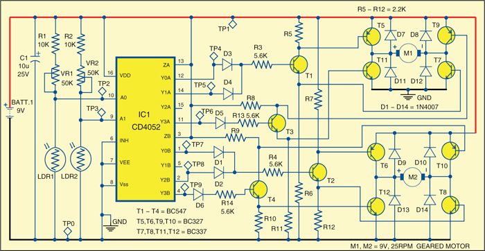
As mentioned earlier, there are two H-bridge circuits to drive the two motors. Motor M1 drives the left side, while motor M2 drives the right side. Each H-bridge circuit is built around a pair of npn and pnp transistors as shown in Fig. 1. Each driving transistor has a diode connected between the collector and the emitter to provide protection against the motor’s back EMF spikes when the respective transistor is ‘off.’

The motor-control transistors (T1 through T4) are driven by the output of IC1 via diodes D1 through D6. IC1, in turn, is controlled by light-dependent resistors LDR1 and LDR2 mounted at the front of the robot. LDR1 is on the left side, while LDR2 is on the right side.

When light falls on both the sensors, their resistances are low, pulling A0 and A1 inputs of IC1 towards0V. In this case, IC1 connects output ZA to Y0A, and ZB to Y0B, allowing current to flo through diodes D1 and D3. This turns on transistors T1 and T2, driving both the motors in forward direction. This is the condition when both the sensors don’t detect any obstacle and the robot moves freely in forward direction.
When an obstacle is detected by both the sensors, the resistances of both the LDRs become high, pulling A0 and A1 inputs of IC1 high. In this case, IC1 connects output ZA to Y3A, and ZB to Y3B, allowing current to flowthrough diodes D5 and D6. This, in turn, switches on transistors T3 and T4, running both the motors in reverse and causing the robot to back away from the obstacle in front of it.
If the light level at LDR1 (at the left side of the robot) falls dramatically due to some obstacle, A0 input of IC1 goes high. In this case, ZA is connected to Y1A, and ZB to Y1B. T1 remains on, so motor M1 continues to run forward. But as the current flow through D1 ceases, T2 turns off and motor M2 stops. As a result, the robot turns to the right, away from the detected obstacle. Similarly, the robot turns left if it detects an obstacle on the right.
Working of the circuit is simple. The robot moves freely in forward direction as long as it doesn’t detect any obstacle. It moves away from any obstacle and navigates its way using the inputs from the LDR sensors.
Construction and testing
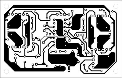
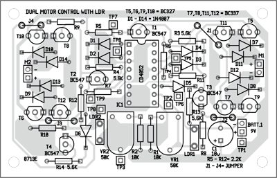
An actual size, single-side PCB for the dual motor control is shown in Fig. 2 and its component layout in Fig. 3. Assemble the circuit on the PCB to save time and minimise assembly errors. Carefully assemble the components and double check for any overlooked error.
During physical testing of the robot, it was found that the motor control works best when both the LDRs are placed on the front side and bent a little outwards (left LDR to the left and the right LDR to the right).
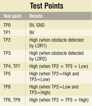
To test the circuit for proper functioning, check correct power supply at TP1 with respect to TP0.
Now put an obstacle in front of the LDRs and check change in the voltage levels at TP2 and TP3 as shown in the test point table. With change in the levels at TP2 and TP3, observe corresponding changes on the output side of IC1 as well by monitoring test points TP4 through TP9.