

A 24-V reference design controls two BLDC motors using different drive methods for pumps used in appliances and other equipment.
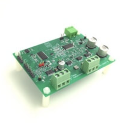
Texas Instruments (TI) has a reference design for controlling two low-voltage brushless DC (BLDC) motors from a 24-V DC supply. The TIDA-00447 combines a 100-W motor drive for a water circulation pump and a 30-W motor drive for a drain pump, targeting applications such as dishwashers and other appliances that use 24-V DC pumps or fans. The complete control unit measures 94 × 65 mm and can deliver up to 130 W of continuous output across the two motor stages.
The design uses two different motor-control approaches on the same platform. The 100-W stage uses a microcontroller (MCU), an external three-phase gate driver, external power MOSFETs, and current sensing. The 30-W stage uses a single motor-driver IC with integrated power MOSFETs. This allows the reference design to demonstrate both a discrete architecture that can be scaled for different power levels and an integrated solution for lower-power motors.
For the circulation pump, the 100-W stage operates from a 24-V DC input, with a maximum input voltage of 30 V and a continuous current rating of 4.5 A. It uses 120-degree trapezoidal control with sensorless back-electromotive-force (BEMF) integration implemented in an MSP430 MCU. TI’s InstaSPIN-BLDC software handles motor commutation. The design supports speeds up to 2400 rpm and includes overcurrent, motor-lock, voltage-surge, undervoltage lockout, and thermal-shutdown protection.
The external MOSFET and gate-driver arrangement gives designers more flexibility when changing the power stage. According to TI, the architecture can be scaled up or down with relatively few changes. The gate driver also provides current-sensing and protection functions, while the PCB uses the MOSFET package and board layout for thermal management.
The 30-W drain-pump stage takes a different approach. It uses the DRV10983, a single-chip three-phase motor driver with integrated power MOSFETs and sensorless control. The device provides continuous 180-degree sinusoidal control and can operate with motors having sinusoidal BEMF, including permanent magnet synchronous motors. The stage is rated for 1.5 A continuous current and has a maximum speed of 2400 rpm.
The lower-power stage also integrates a 5-V/3.3-V buck or linear regulator and protection functions including overcurrent protection, voltage-surge protection, undervoltage lockout, motor-lock detection, and thermal shutdown. This reduces the number of external components required around the motor-control section.
Both motor stages are designed for an ambient temperature range of –10°C to 55°C. The board also includes an isolated UART interface for communication with a main controller, along with temperature monitoring and supply protection. TI tested the design for full-load operation, overcurrent protection, and motor-stall conditions.
The reference design shows how a 24-V motor architecture can be used for appliance pumps instead of high-voltage motor systems. Its two-stage approach also gives designers a way to compare a scalable discrete motor drive with a more integrated solution for lower-power applications.
TI has tested this reference design. It comes with a bill of materials (BOM), schematics, assembly drawing, printed circuit board (PCB) layout, and more. The company’s website has additional data about the reference design. To read more about this reference design, click here.