


This simple circuit of a duophone allows you to access two telephone lines through one telephone set. Each telephone conversation will remain entirely separate unless you choose to combine the two lines through a conference switch. Its unique feature is a three-party conversation/conference facility.
The entire circuit is divided into three main sections- the ringer, hold and conferencing. The telephone set is connected to line 1 under normal conditions. The ringer is used for indicating a call on line 2 that is not connected to the telephone receiver. When you have a call on line 2, the ringer will buzz. The telephone receiver can then be connected to line 2 through the telephone changeover switch S4 to receive the call.
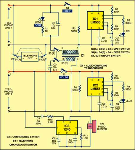
Duophone circuit
Ringer section
The ringer section is built around IC3 and its associated components. Its circuit uses IC 1240 to detect the ring signal and keeps the buzzer ringing for an incoming call on line 2. The supply voltage for the ringer is obtained from the phone line’s AC ring (80V AC RMS) signal and is regulated inside the IC so that the noise on the line does not affect the operation of the IC. The two-tone frequencies generated are switched by an internal oscillator in a fast sequence, which appears at the output amplifier and drives the piezo buzzer element directly.

Hold section
The hold section is built around IC1 and IC2. Switch S1 is used to hold line 1 and S2 is used to put line 2 on hold. Since one telephone set is used for two separate lines, provision is thus made to hold the first call while the telephone set is connected to make or receive the second call.
The circuit comprises two identical hold circuits, each with its own flashing LED to maintain the holding current. Each hold circuit has a timer LM555 (IC1 or IC2) connected as a free-running oscillator operating at a frequency of 2 Hz. The output pin 3 of each timer is used for driving an LED that flashes twice in a second. The hold circuit is powered by the telephone lines through manually-operated hold switches (S1 and S2). Resistors R2 and R6 are placed in the hold circuits to ensure that sufficient current is drawn from the telephone line to prevent a disconnection.

The conferencing section is built around the audio coupling transformer X1. Switch S3 enables three-way conversation through both the telephone lines. The transformer couples the audio signals from one telephone line to the other. At the same time, complete DC isolation is maintained between both the telephone lines. Capacitors C1 and C3 are used for preventing any DC from flowing into the transformer windings. Resistor R1 provides a holding current on line 1 when the telephone set is connected to line 2 during a conference call. Once the three-way conversation is established through the double-pole single-throw (DPST) switch S3, the hold circuits and flashing LED indicators are turned off. LED3, which gets illuminated by the holding current through R1, provides a visual indication of the conferencing.
Circuit operation
The working of the circuit is simple. To check if the wiring of switch S4 is correct, connect the telephone set to line 1. Now lift up the handset and dial the number of line 2. the ringer would sound. Now disconnect line 1 and connect line 2 through switch S4. You would get the dial tone from line 2.
To check a conference call, you would need the help of two friends. First, connect switch S4 to line 1 and make a call to friend 1. Now flip the DPST switch S3 to the ‘on’ position. This puts on hold friend 1 on line 1 and the conference LED3 lights up. Connect switch S4 to line 2 and dial friend 2. When the call on line 2 is answered, a three-way conversation can be made.
When the duophone is not in use, connect switch S4 to line 1. All other switches should be in the ‘off’ mode and all LEDs should be unlit. This permits the telephone ringer to be activated if a call comes on line 2. For making calls using line 1 or line 2, you can simply connect switch S4 to the desired line.
Construction & testing
Assemble the circuit on a general-purpose PCB and enclose it in a suitable cabinet. Fix the switches S1 through S4 on the front side of the cabinet. Also, fix the LEDs on the front of the cabinet and the buzzer at the back of the cabinet. It would be better if you use telephone sockets for the telephone lines. Sockets are relatively inexpensive and save time when troubleshooting needs to be done. Use modular plugs to connect the circuit and the two telephone lines. By using such ‘quick disconnect’ plugs, you can easily remove the unit from the telephone lines. Check the polarity of the telephone lines with a multimeter and connect it to the circuit accordingly.
To check the circuit after completing the wiring, connect a 6V regulated power supply to line 1. When you switch S1 to the ‘on’ position, LED1 blinks at a rate of 2 Hz. If you flip switch S1 to the ‘off’ position and switch S3 to the ‘on’ position, LED1 stops blinking and LED3 starts glowing, indicating that the conferencing facility is being used. Now disconnect line 1 from the 6V power supply, connect it to line 2 and flip switch S2 to the ‘on’ position. Now LED2 blinks at a rate of 2 Hz. Before connecting the circuit to the telephone lines, flip each hold switch to the ‘off’ position. Now your circuit is ready to be used.
The article was first published in November 2009 and has recently been updated.

Sir,it will work for intercom???
May i know what is the rating of audio coupling transformer??