


 Home burglary incidents are on the rise. Homes without proper security measures in place are particularly more vulnerable. But, it is easy to avoid home break-ins by using a simple solution like the electronic door lock presented here. With this circuit installed, the entry door of your house can be unlocked only by entering a pre-decided password, which helps to prevent unauthorised unlocking. The circuit is very simple and can be assembled using readily available components.
Circuit and working
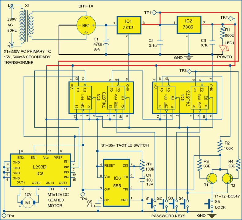
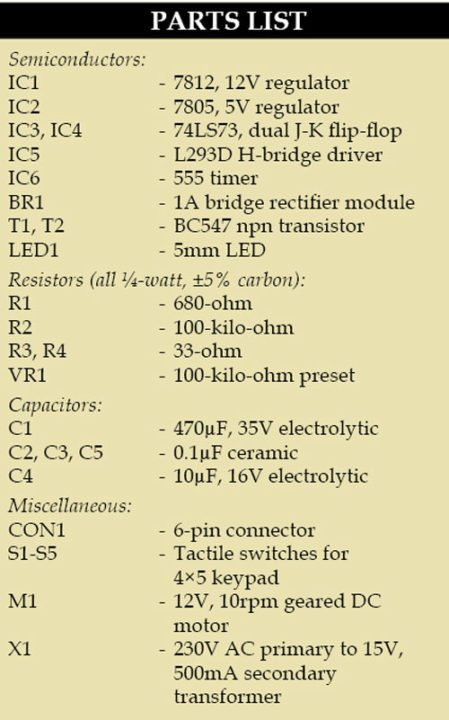
Fig. 1 shows the circuit of the electronic door lock. The circuit is built around dual J-K flip-flop 74LS73 (IC3 and IC4), regulators 7812 and 7805 (IC1 and IC2, respectively), 555 timer (IC6) and a few other components.
The circuit requires 12V for driving motor M1 and 5V for powering rest of the circuit. The mains power supply is stepped down to 15V, 500mA by transformer X1. This stepped-down AC voltage is rectified by bridge rectifier BR1 and filtered by capacitor C1 before it is fed to IC1. Regulator IC1 provides regulated 12V DC supply, which is further fed to IC2 to get 5V supply. The glowing of LED1 indicates the presence of power in the circuit.

The door opens when switches S1 through S4 are sequentially pressed. The password is recognised using three flip-flops and transistor T2. Flip-flop FF2 of IC3 is operated in toggle mode by making J2=K2=1 (high).
 When S1 is pressed, a ground pulse is provided by the keypad, which makes the output of flip-flop (FF2 of IC3) toggle from logic 0 to 1. This pulls up the inputs of flip-flop FF1 of IC4 to high, thus making it also operate in toggle mode.
When switch S2 is pressed, flip-flop FF1 of IC4 toggles from logic 0 to 1, which, in turn, puts FF2 of IC4 in toggle mode.
When switch S3 is pressed, flip-flop FF2 of IC4 toggles from logic 0 to 1. This provides a positive bias to the base of transistor T2.
Now when switch S4 is pressed, the emitter of T2 is pulled to ground momentarily. At this point, transistor T2 is driven into saturation. This clears all the flip-flops and triggers 555 timer (IC6) simultaneously.
Timer IC6 is configured in monostable mode. It provides an output pulse of predefined width, which simultaneously clocks flip-flop FF1 of IC3 and enables the H-bridge. This rotates the motor for the predefined period to unlock the door.
To lock the door back again, just press switch S5. This triggers IC6, which, in turn, toggles flip-flop FF1 of IC3, rotating the motor in reverse direction for the same period of time.
Working of the project is simple. When the keys are pressed in the sequence S1-S2-S3-S4, the door unlocks. These keys can be connected to any numbers on the keypad, thus making your password. To lock the door, just press S5.
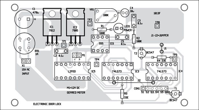
Construction and testing
An actual-size, single-side PCB for the electronic door lock circuit is shown in Fig. 2 and its component layout in Fig. 3. Assemble the circuit on the PCB to minimise assembly errors. Take any 4×5 numeric keypad and connect five of its keys to the PCB at CON1 (refer Fig. 1 for connections). Please note, pressing the right sequence of keys corresponding to S1-S2-S3-S4 is necessary for unlocking the door.
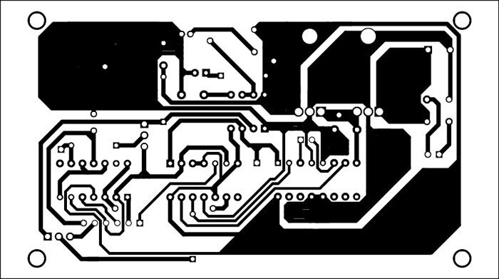
Download PCB and Component Layout PDFs: Click here
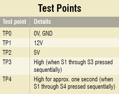
To test the circuit for proper functioning, verify 12V power supply at TP1 and 5V power supply at TP2 with respect to TP0. Press S1 through S3 sequentially and check high level at TP3. Now press S4 and check the output of IC6. It should be high for a time period decided by the timing components.
The author is a third-year BE student at Vidyavardhaka College of Engineering, Mysore

Very useful
Thank you.
Sir,can you please give me the instruction for changing the p
password
On a Numeric Keypad (Keypad with numbers from 0 – 9), the password keys S1 to S4 can be assigned to any 4 numbers (maybe by putting stickers on the numbers etc). The remaining numbers on the keypad will be dummy. So, to change the password, just assign password keys to different numbers. That’s it. No change to circuit is necessary.
what if someone forgots the password and wants to reset it
Is this project is tested for working.I simulate it but t2 is not driven into saturation.please reply,its emergency..
Yes, the project is tested and it works as expected.