


 An electroscope is the instrument used to detect charged bodies. Here is an electronic version of the scope that is sensitive and, unlike conventional scopes, indicates the polarity of charge as well. This circuit consumes very low quiescent power and reliably indicates charge induction and detection. The polarity of charge is indicated through LEDs (green LED indicates positive and red LED negative).
As shown in Fig. 1, the circuit is built around popular dual timer 556 (IC1), quad 2-input NAND gate CD4011 (IC2), transistors BC547 and BC557, and a few discrete components. The CD4011 has four NAND gates with very high input impedance. This high impedance is used in detecting the potential difference produced by an external charge distribution.
When the positively charged object is brought near the positive-detecting plate, it attracts electrons from the detector plate and hence capacitor C6 becomes positively charged.

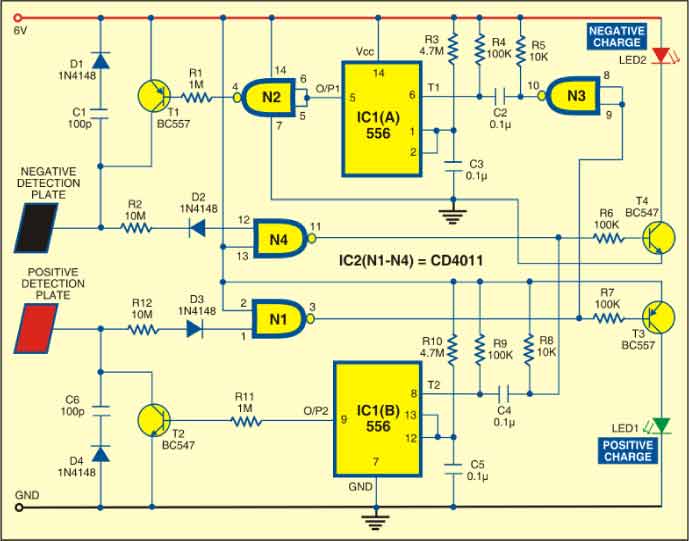
Diodes D3 and D4 (1N4148) help determine the direction of current flow, removing certain shortcomings of the circuit. (These prevent the capacitor of the opposite arm from charging when the object is withdrawn quickly.) Even though diode D4 in series with capacitor C6 is reverse biased, the current through it is adequate to charge capacitor C6. Thus capacitor C6 gets charged with respect to the ground and the input voltage of gate N1 goes high. This makes the gate output low and transistor T3 conducts to light up the green LED.
The process is similar during negative charge detection. Here transistor T4 conducts to light up the red LED.
When a negatively charged object is brought near the detecting plate, it also affects the positive-detecting plate. The negatively charged object pushes the electrons in the positive-detecting plate towards its input capacitor and the plate becomes negatively charged with respect to the ground. These electrons leak through the gate input into the other parts of the circuit.
When the negatively charged object is withdrawn, the positive-detecting side having lost electrons (detecting plates and the capacitor) appears to be positively charged. Since this voltage may not exceed the supply voltage (V+0.6), the gate will not conduct heavily to return the electrons immediately. In this case, the charge developed across the capacitor takes a long time to decay and the gate becomes locked.
To overcome this problem, two monostable multivibrators built around IC1(A) and IC1(B) have been incorporated for each arm. The high output of monostable IC1(B) shorts capacitor C6 to the ground for a specific time as soon as the output of the negative-sensing gate (N4) goes from high to low. Similarly, the high output of IC1(A) charges capacitor C1 for a specific time as soon as the output of the positive-sensing gate (N1) goes from low to high.
A similar arrangement is provided for both the positive- and negative-detecting sides. So when a positively charged object is withdrawn, the negative-charge-detecting input capacitor is shorted. The monostables prevent locking of any of the two gates and allow the scope to function smoothly.
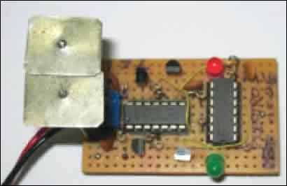
The electroscope can be designed for bench-mounting or more compactly inside a gluestick tube with identical metallic detector plates on the cap. Two CR2032 (3V) cells are used to power the circuit. Take the tube slowly towards the charged object or bring the object slowly towards the scope. Either of the two LEDs will glow depending on the polarity of the charge on the object. The author’s prototype is shown in Fig. 2.To test the circuit after construction, whack your hair with a comb and bring the comb near the scope slowly. The red LED should glow to indicate a negative charge. This glow should be constant as long as the comb is near the detecting plates.
It is also possible to use the scope as a direct charge detector within limits by bringing the corresponding plates (or just the lead) in direct contact with the point of charge accumulation in a circuit. The sensitivity can be increased to some extent by decreasing the values of capacitors C1 and C6.
EFY note. external reset can be provided using an SPDT switch (not shown in the circuit) between the output of the monostable and the 1-mega-ohm resistor, with its pole connected to the 1-mega-ohm end. Connect one throw to the monostable and the other to +V or 0, as per the transistor.
Thank you ,
That is a intrest circuit
You are most welcome.
Are the two detection plates touching each other, or separated? Hard to see in the picture, but I believe they are touching and completing the circuit?
No, they are not.
What would happen if I replaced the plates with aluminium foil?