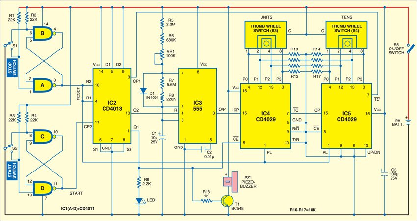
 This easy-to-build electronic alarm will remind you of an impotant task after a preset time. It is particularly useful for housewives and busy professionals. All you have to do is set the time in minute swith the help of two thumbwheel switches (S3 and S4) and press and release start switch. Precisely after the time set by you is over, there is an audio as well as visual indication to remind you that the time you set has elapsed. The gadget is portable and operates off a 9V battery.
At the heart of this circuit are two counter ICs CD4029 (IC4 and IC5). These are programmable up/down 4bit binary/decade counters belonging to CMOS family of digital integrated circuits. The information present on them is fed to inputs P0 through P3 in parallel. It is loaded into the counter when the PL input is high, independent of the clock pulse input. In this circuit, IC4 and IC5 count in up/down mode when the up/down input is high/low. These have been wired as 4-bit binary counters in countdown mode with B/D input low. The counter advances by one count on every low-to-high transition of the clock pulse.

The output terminal TC, which is associated with counting, is usually high. It goes low when the counter reaches its maximum count (if wired in ‘up’ mode) or minimum count (if wired in ‘down’ mode), and goes high again immediately following clock transition. The clock-enable (CE) input is an active-’low’ input as indicated by the bar, i.e., the clock pluses will be enabled only when this input is low.
IC2 (CD4013) is a dual D-type flip-flop with each D flip-flop inside it having independent data, clock, set and reset inputs. The data bit (low or high) on the D-input is transferred to the output on low-to-high transition of the clock input. Set and reset are asynchronous inputs and activated with a high on these lines. This implies that when the set input is high, the Q output is high irrespective of the logic status of the ‘D’ input and clock transitions. Similarly, when reset is high, it overrides all other information and forces the Q output to low state.
IC3 (timer 555) is wired as an astable multivibrator with its output waveform having a time period of one minute. For timing accuracy and stability, resistors R5 and R6 should preferably be metal-film resistors and C1 a tantalum capacitor.
IC1 (CD4011B) is a quad 2-input NAND gate. Two of these four NAND gates (A and B) with pull-up resistors R1 and R2 constitute the de-bouncing circuit for micro-switch S1, which generates the master reset pulse every time it is pressed and released. The remaining two NAND gates (C and D) along with resistors R3 and R4 make up the other debouncing circuit for micro-switch S2, which generates the start pulse when it is pressed and released.
The circuit operates as follows: Initially, the position of micro-switches S1 and S2 is such that both reset and start outputs are low. First, set the timing (in minutes) with the help of two BCD switches, also known as thumbwheel switches, S3 and S4. If you select ‘5’ through thumbwheel switch S3 and ‘6’ through thumbwheel switch S4, the time delay is set at 65 minutes. The second step is to press and release micro-switch S1. A positive-going pulse resets flip-flop IC2 and also loads the programmed time delay information into counters IC4 and IC5. Since Q2 output of IC2 is initially low, when we press and release start switch S2, IC2 gets clocked and its Q2 output goes high. Reset pin 4 of timer IC3 gets supply to activate it. This is the time when the time delay begins to count-down.
To summarise, in order to use the reminder gadget, set the time delay after which you would like to be reminded, press and release switch S1 followed by a similar operation of switch S2.
TC output of IC5 is normally high and goes low when start switch S2 is pressed. It would go high only after 65 minutes if the time set by thumbwheel switches S4 and S5 is 65 minutes. This is basically a 65-clock cycle. Remember that the time period of IC3 is approximately one minute. This pulse appearing at the output (TC) of IC5 clocks at CP1 of IC2, whose output goes from low to high and drives both LED1 and piezobuzzer PZ1 to ‘on’ state.
The Q1 output of IC2 also forces clock-enable (CE) input of IC4 to go high and disable the clock. LED1 and piezobuzzer PZ1 remain ‘on’ unless you reset the system through switch S5. After the system is reset, the gadget is ready for a fresh time setting.


What is vr1 in the above electronic reminder circuit