Those who are following the author’s series of articles would have seen the design of the charge controller in the previous article. In that article, the design of the charge controller is a fully functional one, but it lacks safety features. Let’s understand product risk analysis.
A good product should not only function properly but must be robust. A well-designed product will accept a certain amount of abuse and will continue to perform nicely. Such fault-tolerant products are loved by the customers.
Any product will face variations from the design conditions during manufacture and use. Normally designers specify the tolerance limits of the design parameters, but a product design needs to be checked for proper performance with the worst-case scenario of the process variations.

Apart from the designed tolerances, the product may be used in a different manner than the designer had planned. A robust product will anticipate those unintended uses and provide features for such uses. The product should also have safety features to prevent damage or minimize damage due to any unplanned usage.
We must appreciate that our effort to make the product robust comes at a cost. In most cases, such a change will add to the cost, weight, and probably size of the product. Customers do not like to pay extra for things that are not directly delivering value. A good design becomes an art of compromise on cost versus quality.
We need to understand the effects of various risks and prioritize our budget. We need to understand which failures are important and which can be ignored. The systematic evaluation of such risk and its effect is called failure mode effect analysis (FMEA).
FMEA (Failure Modes and Effects Analysis)
Several things can go wrong with a product. Our analysis begins with identifying what can go wrong with the product. There can be various ways to identify these possible failure modes.
My favorite option is to sit together with the development team and examine each of the subsystems to find things that can go wrong. Once the team has listed all that can go wrong in each of the subsystems, we start examining things that can go wrong with interactions of the subsystems.
One should note that all problems are not equally important. Events that can cause life risk or big financial loss have to be given higher priority than a problem that will cause minor irritation.
Similarly, problems that are very likely to happen need to be addressed with higher priority than a problem that has a very rare chance of occurring. Defects that are difficult to identify, need to be given higher priority than defects that are easy to identify.
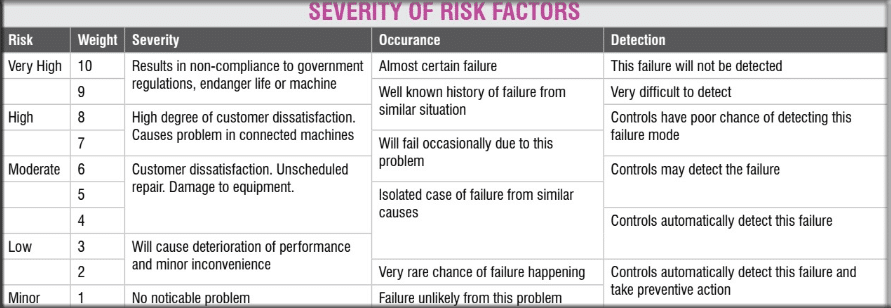
Once we list the possible issues, we need to understand their effects, the probability of such events occurring, and the difficulty in detecting the issues. For each of the impact, probability, and detection we assign a subjective number according to the scale given in Table 1. Multiplication of these three numbers gives us the risk priority number (RPN).
Types of Risk
Product risks can be of a technical nature, they can be economic, or they can be related to the supply chain. Design deficiency, changes in input conditions, environmental factors, and the quality of input materials are technical risks.
Some of the technical risks can lead to accidents, where the impact can extend beyond the application area of the product. For this reason, technical risks need to be given higher priority in the analysis.
Economic risks cause a loss of profitability or may cause higher operating costs. In both cases, the business viability of the product suffers. Typical reasons for economic risks are price escalation, unplanned operating expenditure, or poor quality of supply. In some cases, frequent breakdowns due to technical faults may also result in economic risk.
The third kind of risk arises from supply-chain issues. Depending on unreliable vendors, insufficient product volume, or product complexities often result in the suppliers not supplying the material. Supply-chain risks may call for costly alternatives, redesign of the product, or cause closure of its production.
Just like the product design, one has to be careful with vendor development or work with standard easily available raw materials.
As a general guideline, any risk with an RPN number higher than 400 is not acceptable. Such risks have to be reduced by redesigning or by adding protective measures. One may ignore the risks with an RPN value of less than 120 and focus on reducing other higher-priority risks. Risks with RPN values below 240 are somewhat tolerable.
Risks with RPN between 240 and 400 should be reduced. Such risks should be accepted only when the design team cannot come up with any feasible measure to reduce the risk.
Risk Mitigation Approaches
Risk mitigation can be done by various means. The aim of all the means is to reduce the RPN value. The best way for risk reduction is to either eliminate it or reduce the chance of it happening.
This can be achieved by adding some safety margin in the design, by providing parallel sub-systems, or by providing an auxiliary system that automatically takes over in the event of failure of the main system.
In addition to risk prevention measures, we can try to reduce the impact of the risk. We are all familiar with the fuse or circuit breakers in our domestic electric wiring. These fuses stop the electric supply in case of any high current flow and prevent overheating and fire risks in the house.
In product design, we often provide a ‘fuse.’ These are intentional weak points in the design that break down during any unplanned situation and prevent further damage to the system.
One must remember that fuse is a disruptive solution. Too much use of fuses is not good. As far as possible, one should use other innovative approaches to reduce damage and use a fuse only as the last resort.
Alarms and warnings are notifications for human intervention during emergency conditions. Such devices improve the detection of faults. When the product is not able to cope with certain unnatural conditions, it can give a warning to the user to take some action.
One must remember the importance of the signifier that we discussed in our first article.
Alarms and warnings must give clear information on what the user should do to deal with the emergency. The control panel or the interface needs to be suitably designed to eliminate any ambiguity between the warning and the desired action.
Product Risk Analysis – Example
Let us examine our charge controller for various types of risks. The problems can happen due to missing connections with the external parts. We can also have situations of some modules fail.
As our production volume is expected to be small, we also have a risk of some of the modules being phased out by the respective manufacturer as well as price escalation.
On the economic front, there can be a risk of competition. There is also the risk of low market demand, which may adversely affect the business viability.
In addition, we may get risk from the environmental conditions. Gusty winds may cause the wind turbine to generate higher power and voltage. If these are not controlled, it may damage the controller as well as the battery and alternator.
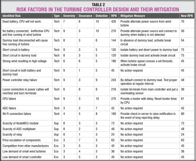
We list all these risks in Table 2 and analyze them for occurrence, severity, and detection as we have discussed earlier. For the risks with higher RPN numbers, we plan measures to reduce the risk.
The mitigation measures are also listed in the same table. Once we have reduced all risk RPN values to an acceptable limit, we can finalize our design.
Circuit Design
From the mitigation measures decided, we need to find the design changes that are required. Most of the recommended changes require implementation in the program logic.
On the circuit design, we need to provide a power supply to the controller from both the battery and the wind turbine. We also need to add a hooter that will get activated in the event of the controller CPU stopping.
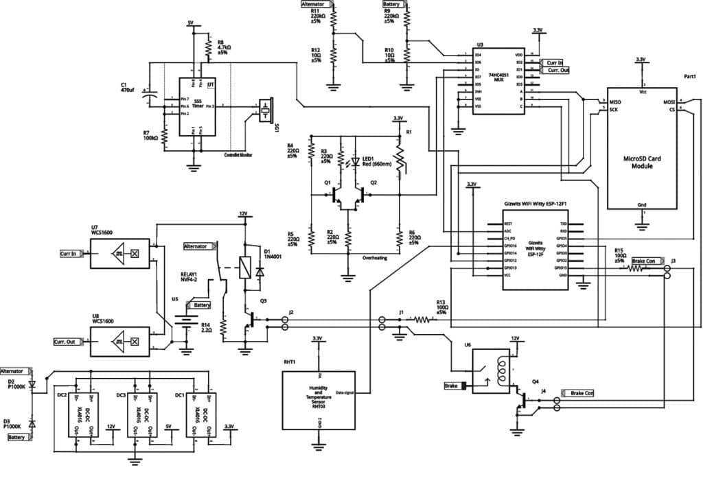
We have identified the best options for submodules assessed various risks and made our product robust. With these inputs, we can now start making the schematic circuit diagram.
The heart of the circuit is the ESP8266-based ESP12F module. This has only one ADC sensor, hence we use an analog multiplexer 75HC4051 (U3) to read the battery and wind turbine voltages.
Voltages in both of these are higher than the operating range of the microcontroller, hence we use a voltage divider circuit comprising resistors R9, R10 and R11, R12 to reduce the voltage to the operating level.
The current flow in the power section is high. We use non-contact Hall effect sensors, U7 and U8, to read the current flowing from the wind turbine and from the battery. These produce a voltage proportional to the current flow, which is fed to U3.
For safety, the power controller relays will be kept separate from the main controller. We use an NTC sensor to sense any overheating in the power module. In case of any temperature rise, the NTC resistance will drop and the voltage in the junction of R1 and R6 will rise.
This is sensed by a simple voltage comparator comprising Q1, Q2, and R2 to trigger the overheating indicator LED1. The junction voltage is also fed to U3 and monitored by the CPU.
The charge controller uses an SD card to store charging and discharging data. The SD card read-write module uses the SPI protocol. ESP12F has 16 GPIO pins but most of these pins are also used for internal operations. Not many pins can be used safely for control operation.
To preserve the pins, we repurpose the SPI communication pins to control the analog multiplexer. As reading analog signals and writing values to SD cards are mutually exclusive, this design is safe.
We use GPIO pins 4 and 5 to control the battery charging and brake relay operation. We use a buzzer to give a warning for CPU malfunction. The buzzer is activated by a 555 timer-based delay circuit.
Under normal situations, the CPU will reset the delay in its operating cycle, which will be several times every second. If the 555 is not reset in about 52 seconds, it will trigger the buzzer to give an audible warning of CPU malfunction.
The components are powered by both alternator and battery to ensure a reliable power supply. The supply voltage is around 48V. For our operations, we need supply at 3.3V, 5V, and 12V. We use three DC-DC converters to get these voltages efficiently.
The addition of safety features to detect and prevent serious problems in the design will make the product more robust and improve its safety.
In our next article, we shall discuss how to address the effect of unknown variables and the controller logic program.
The author Soumyanath Chatterjee is a former TVS Motors Chair Professor at the Industrial and Systems Engineering Department, IIT Kharagpur. His expertise is in Product Development and Supply Chain Management