


We designed our own Environment Sensor Module and here we are going to explain step-by-step how you can also make this at your home.
BME688 is a digital environmental sensor developed by Bosch Sensortec. It is part of the BME series, which includes sensors designed to measure multiple environmental parameters.
The BME688, in particular, is capable of measuring temperature, humidity, barometric pressure, gas resistance, and air quality all packed in small sizes making it good for many environmental projects and wearable devices.

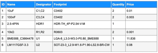
Bill of Material
Setting Up Environment Sensor IC
According to the BME688 IC Datasheet, the sensor IC can be powered within the range of 1.7 to 3.6V. To ensure compatibility with most development boards, we’ve opted for a 3.3V power supply, a widely available voltage level.
To achieve this, we’ve integrated a 3.3V voltage regulator IC along with two ceramic capacitors. This setup effectively regulates the input voltage of 12V to a stable 3.3V, providing reliable power to the sensor module.


For the sensor’s interface, we had two options: SPI and I2C. We decided to go with I2C due to its simplicity in terms of GPIO requirements and connections.
The datasheet mentions that the I2C address can be modified using the SDO pin. In our design, we’ve chosen to fix the I2C address by directly connecting the SDO pin to the GND pin.

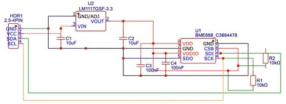
Environment Sensor Module – Circuit Design
In the final breakout sensor circuit, we connect the regulated 3.3V output from the voltage regulator to the sensor’s power input pin, ensuring a solid ground connection.
Additionally, we’ve added two 10K pull-up resistors to the SDI and SCK pins, a standard practice for stable I2C communication. The output pins, SDA and SCL, are connected to a jumper header connector, simplifying connections to a microcontroller.
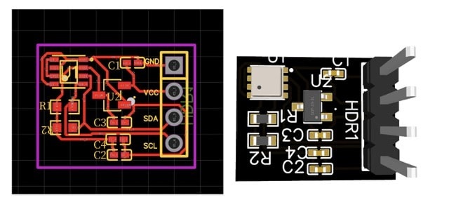
PCB Design and Testing
To bring this design to life, you’ll need to create a PCB layout based on the circuit design. For testing, connect the module to any Arduino or compatible microcontroller using the I2C pins.
Install the BME688 library in the Arduino IDE and upload the provided test code to observe sensor readings. In case you encounter issues with sensor data, you can use an I2C scanner code to confirm correct connections and identify the module’s address.
This design is both practical and versatile, allowing for easy integration of the BME688 sensor IC into various applications.
If you require further information or have specific questions, please feel free to ask in the comment section below.

