


At night when power fails, one finds it difficult to reach the generator to start it. Here is the circuit for a generator room light that automatically turns on at night, facilitating easy access to the generator. During daytime, the light remains off.
Generator room light circuit
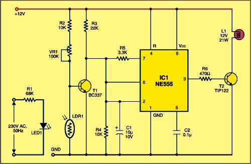
Shown above is the circuit for generator room light, while below is the battery charger circuit, which is optional and can be omitted if the generator is self-start type and has a built-in battery. At the heart of the generator room light circuit (Fig.1) is a light-dependent resistor (LDR1) that senses the ambient light as well as light from glowing LED1.
During daytime, sunlight or light from LED1 reduces the resistance of LDR1. As a result, the voltage drop across LDR1 decreases and NPN transistor T1 does not conduct. The collector of T1 and therefore pins 2 and 6 of IC1 remain high, making output pin 3 of IC1 low and transistor T2 cut-off. So lamp L1 connected between the collector of T1 and the positive terminal of 12V supply does not glow.

As the ambient light fades during sunset, the resistance of LDR1 increases. As a result, the voltage drop across LDR1 increases and NPN transistor T1 conducts. Pins 2 and 6 of IC1 go low to make its output pin 3 high, and lamp L1 glows.You can replace incandescent lamp L1 with bright white LEDs using proper current-limiting resistors.
Construction & testing
Assemble the circuit on a general-purpose PCB and enclose in a suitable cabinet. Install the unit near the generator. Arrange LED1 and LDR1 such that during the availability of mains, light emitted from LED1 falls directly on LDR1. Also, make sure that during daytime the ambient light falls on the LDR.
Battery charger circuit
For powering the battery charger circuit (Fig. 2), 15V AC secondary voltage is derived from step-down transformer X1. For fast charging of the battery, you may increase the current rating of transformer X1.
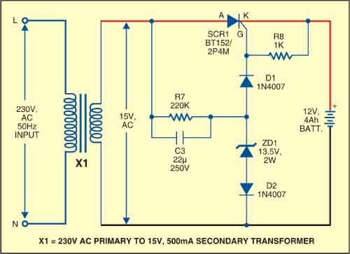
The charger charges the battery through a thyristor (SCR1) when the battery voltage is low. The thyristor gets a regulated gate voltage from the Zener diode and goes to tickle charging mode when the battery voltage nears the Zener voltage.
Construction & testing
Assemble the charger circuit on a general-purpose PCB and enclose in a suitable cabinet. Use two crocodile clips (red for positive and black for negative) for connecting the battery terminal to the charger circuit.
The project was first published in July 2009 and has recently been updated.