


 A friend of mine plays guitar with several guitar effect pedals. He had a problem with battery eliminators and cables of the pedals cluttering the stage and so he asked for help. The solution is simple as described here.
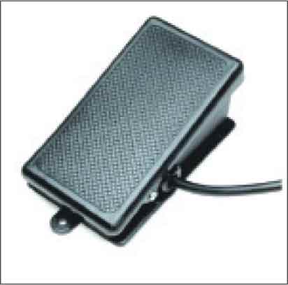
A small box is fitted to the rear of the amplifier providing a 9V output for the effect pedal. The amplifier section gets 9V through a pedal switch (refer Fig. 1). This power output and guitar signal input lines are combined into a single unit with multi-way cable connecting points as shown in Fig. 2.
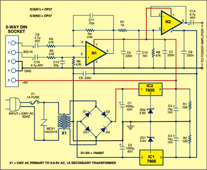
The circuit (Fig. 2) can be divided into two sections: power supply and signal handling. The power supply section is built around transformer X1, regulators 7805 and 7905, bridge rectifier comprising diodes D1 through D4, and a few discrete components. The signal-handling circuit is built around two OP27 op-amps (IC3 and IC4).

The power supply of about 9V for the effect pedals is derived from step-down transformer X1. MOV1 is a metal-oxide varistor that absorbs any large spike in mains power.
IC 7905 (IC1) is a -5V low-power regulator. By using a 3.9V zener diode (ZD1) at its ground terminal, you get -8.9V output. The same technique is also applied to IC 7805 (IC2)-a +5V regulator to get 8.9V. Use good-quality components and heat-sinks for the regulators. This supply is more than enough for the five effect pedals.
The greater the voltage drop across the regulator, the lower the output current potential. Resistors R1 and R2 provide a constant load to ensure that the regulators keep regulating. Capacitors C3 through C8 ensure that the supplies are as clean as possible. It is very important to use proper heat-sinks for IC1 and IC2. Otherwise, these could heat up.
Working of the circuit is simple. The input signal stage uses a basic differentiation amplifier to accept the incoming signal and a voltage follower to buffer the output to the power amplifier. The differential amplifier is built around IC3. It works by effectively looking at the signals presented to its inputs. If the input signals are of different amplitudes, IC3 amplifies the difference by a factor determined by R4/R3 (where R4=R6 and R3=R5). If the input signals have same amplitudes, these are attenuated by the common-mode rejection ratio (CMRR) of the circuit. The value of CMRR is determined by the choice of the op-amp the auxiliary components used and circuit topology. You can use standard resistors. With the values shown, you get an overall gain of unity.
The combination of resistor R7 and C13 serves as a passive low-pass filter, progressively attenuating unwanted high-frequency signals. The second op-amp (IC4) forms a simple voltage follower (its output follows its input), providing a low output impedance to drive into the standard power amplifier.
Assemble the circuit on a general-purpose PCB and fit it to the rear of an amplifier. The unit must be compact, yet robust. So use a very sturdy aluminium extrusion for the cabinet in order to neatly house the assembled PCB.
To ensure simple operation, there are only three connections to the unit. First, mains power is tapped from the transformer. The second lead carries the 9V output to the amplifier. The third is the guitar signal input at the five-way socket for connection to the effect pedal.