


 For beginners, here’s a low-cost multitester that can be used to test the condition of almost all the electronic components from resistors to ICs. It uses only a few components but can also detect polarity, continuity, logic states and activity of multivibrators.
The circuit is extremely simple and exploits the biasing property of bipolar transistors. Transistors T1 and T2 act as transistor switches driving the red and green halves of bicolour LED1 independently to give results of the test.
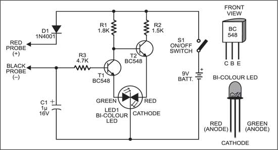
Working of a Multitester
When power is applied by pressing switch S1, transistor T1 stops conducting due to the lack of forward bias. At the same time, transistor T2 takes base bias voltage from the battery through resistor R1 and conducts. This allows the red half of bicolour LED1 to illuminate.

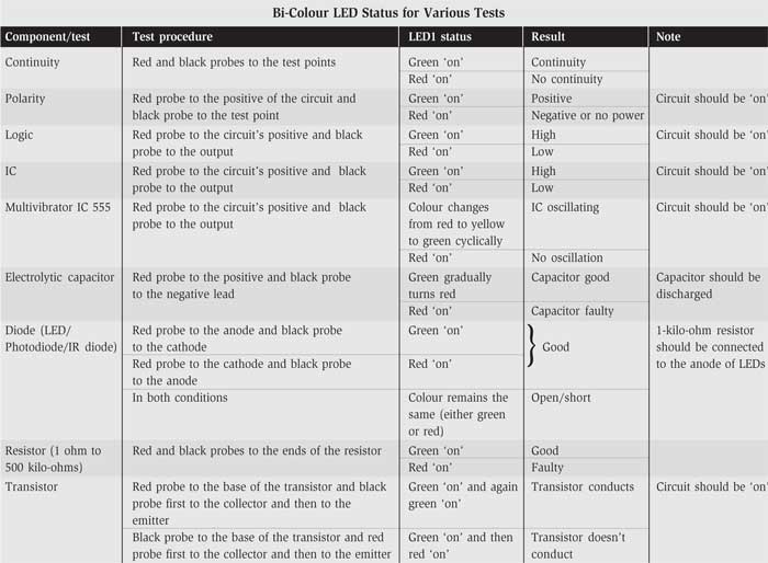
When the base of transistor T1 gets positive voltage through resistor R3, it conducts to light up the green half of bicolour LED1. When transistor T1 conducts, the base of transistor T2 is grounded and it cuts off to turn off the red half of bicolour LED1. The functioning of the circuit thus depends on the signal obtained at the base of transistor T1. The table gives the testing procedures for various components with the expected indications/results.

does this circuit actually work????
Yes, this circuit is verified by EFY Team.
I guess I can add a buzzer to the red light to help signify danger
How can i create this on proteus?
I have common anode four pin rgb LEDs what is circuit?
Steven