


 This 5-color LED flasher circuit can be built using the popular 555 timer and 4017 decade counter ICs. It does not require any expensive components like a microcontroller.
The timer IC is used as an astable multivibrator to generate a clock pulse, which is fed to the clock input of the 4017. Outputs of the 4017 are connected to bases of five transistors to drive 20 LEDs of different colors, each with its current-limiting resistor.
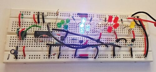
The 4017 advances to the next output every time it receives a clock pulse, causing the LEDs to turn on and off in sequence. The speed of the flashing can be adjusted by changing the values of the resistors and capacitors in the 555 timer circuit. The author’s prototype is shown in Fig. 1.

POC Video Tutorial In English:
POC Video Tutorial In Hindi:
Required Components
| Parts List | |
| Semiconductors: | |
| IC1 | -555 IC timer |
| IC2 | -4017 decade counter |
| D1-D5 | -1N4148 signal diode |
| LED1-LED4 | -5mm red LED |
| LED5-LED8 | -5mm green LED |
| LED9-LED12 | -5mm blue LED |
| LED13-LED16 | -5mm white LED |
| LED17-LED20 | -5mm yellow LED |
| T1-T5 | -BC548 NPN transistor |
| Resistors (all 1/4-watt, ±5% carbon): | |
| R1 | -10-kilo-ohm |
| R2-R12 | -1-kilo-ohm |
| Capacitors: | |
| C1 | -100nF ceramic disk |
| C2 | -10µF, 25V electrolytic |
| Miscellaneous: | |
| CON1 | -2 pin connector |
| -9V or 12V battery | |
| -Breadboard | |
| -Jumper wires | |
LED Flasher Circuit Diagram

EFY++ CONTENT: ACCESS TO THIS CONTENT IS FREE! BUT YOU NEED TO BE A REGISTERED USER.
Hello,
May I ask what is the purpose of those diode 1N4148?
If it has purpose for reversed current, so I would think that both of the outputs Q1 & Q2,etc… connect to the Anode of the diode.
Please advice,
We thank the reader for detecting this error and sharing with everyone!
Please refer the circuit diagram and connect anodes of 1N4148 diodes to
the outputs of Q1, Q3, Q5, Q7, and Q9—just like the connections to Q0,
Q2, Q4, Q6, and Q8—and the cathodes of 1N4148 diodes to the junctions
before the base bias resistors of respective transistors. Yes, these diodes are
for preventing reversed current.
I am using a simulator to simulate this timer circuit but that simulator decade counter is different than this. Decade counter available in simulator is “74HC4017”. Can you specify the difference because i tried but it didn’t work.
The CD4017 and 74HC4017 are decade counters.They have some differences between them.
1.Technology: The CD4017 is built using CMOS, while the 74HC4017 is CMOS (HC).
2.Voltage Levels: The CD4017 operates at voltage range from 3V to 18V, while 74HC4017 operates at voltage range 2V to 6V.
3.Power Consumption: Due to the difference in technology, the CD4017 generally consumes more power compared to the 74HC4017.
4.Output Current: The CD4017 can provide higher output current than the 74HC4017.
5.The pinout and functionality of the CD4017 and 74HC4017 are similar, but the differences mentioned above should be considered when selecting the appropriate IC for your specific project.
Hi,
You designed good circuit. keep it up. post more projects like this.
Thank you for your feedback.