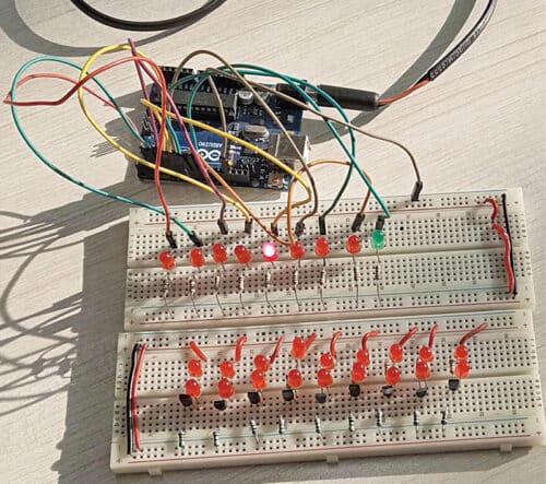
During festivals like Diwali, Christmas, and New Year strings of flashing lights are sometimes used to decorate homes and other premises. Arduino based flashing lights can be made with the help of just a few components for such occasions. The author’s circuit wired on a breadboard for this purpose is shown in Fig. 1.
The circuit diagram of Arduino based flashing light is shown in Fig. 2. The circuit comprises an Arduino Uno board (BOARD1), nine LEDs (LED1 through LED9) to demonstrate the concept, and a few discrete components only.

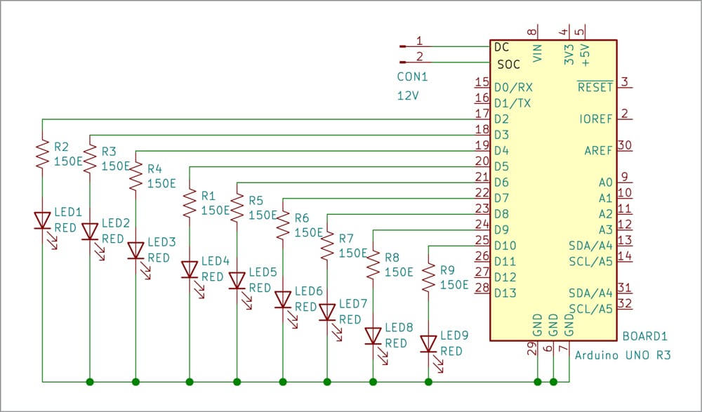
The nine output pins of the Uno board are connected to the nine LEDs, one each, which switch on and switch off at predefined interval. As the high state of an output pin shifts from one pin to another, only one output pin is high at a time and switches on the LED connected to it. Thus, it looks like a running light, which can be arranged in a circle or any other desired shape.
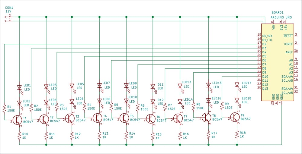
To make a longer string of flashing LEDs, you may use the circuit shown in Fig. 3. This circuit flashes 18 LEDs, for which it makes use of nine NPN transistors in addition to the other components.
In the 18-LED flasher, nine outputs of Arduino Uno are connected to the bases of transistors T1 through T9 via resistors R1 through R9. The outputs go high and low after a predefined time. As before, the high state output shifts from one pin to the other but only one output pin is high at a time. Thus, the output again produces a running light effect.
Resistors R1 through R9, in both the circuits, are used to limit the current passing through each of the LEDs connected to them. To make a longer string, you can experiment with more LEDs in series and reduce the values of resistors R1 through R9 accordingly.
Software
The simple software for this project is written in Arduino IDE version 1.8.5. You can however use any version as it is a very simple program.
When nine LEDs are connected to the Arduino board, these are listed as array “led array [] = {2, 3, 4, 5, 6, 7, 8, 9, 10}”. The “for” loop in program shifts the state of the pins listed in the array with the increment of the variable “i”. Thus, it switches each pin in the array to a high state and low state with a delay of 50ms. So, the pulse switches on only one LED at a time and keeps shifting to the next pin and the LED connected to it.
Before uploading the Sketch program to the Arduino Uno board, do not forget to select the proper port. After selecting proper port, upload the Sketch file flasher.ino to the board.
Construction and testing
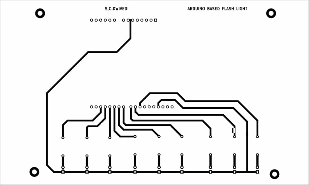
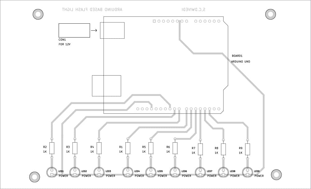
In case you wish to make a PCB for the circuit, its same-size pattern is shown in Fig. 4, while the components layout is shown in Fig. 5. After wiring the circuit, enclose it in a suitable box, including the Arduino Uno board. Solder all the LEDs properly on their footprints (positions) shown in the PCB.
Do not forget to upload the source code (flasher.ino) before assembling the circuit. For uploading the source code use a USB cable, which can also be used to operate this circuit.
| Semiconductors: | |
| Board1 | – Arduino board |
| LED1-LED9 | – 5mm LED |
|
Resistors (all 1/4-watt, ±5% carbon):
|
|
| R1-R9 | – 150-ohm |
| Miscellaneous: | |
| CON1 | – DC socket |
| – Breadboard | |
| – Jumper wires | |
|
Optional – Parts List for Arduino based
|
|
| 18-LED flashing lights string | |
| Semiconductors: | |
| Board1 | – Arduino board |
| LED1-LED18 | – 5mm LED |
|
Resistors (all 1/4-watt, ±5% carbon):
|
|
| R1-R9 | – 150-ohm |
| R8-R10 | – 1-kilo-ohm |
| Miscellaneous: | |
| – Breadboard | |
| – Jumper wires |
If you do not wish to use USB cable to operate the circuit, connect 12V DC from an adaptor across CON1 to operate the circuit.
PCB layout for the circuit in Fig. 3 is not provided here. You can assemble it on a breadboard or a general-purpose.
Download PCB and Component Layout PDFs: click here
Download Source Code
S.C. Dwivedi is an electronics enthusiast and circuit designer at EFY