Accurate 1Hz squarewave pulses are required in stopwatches and other digital circuits. Here is a low-cost, general purpose 1Hz signal generator without using a crystal oscillator.
1Hz signal generator circuit
230V, 50Hz, single phase AC mains is stepped down by centre tapped transformer X1 to deliver a secondary output of 9V-0-9V at 100 mA. The transformer output is rectified by a full-wave rectifier comprising diodes D1 and D2 and filtered by capacitor C1. This provides required DC voltages for operation of the electronic circuit.
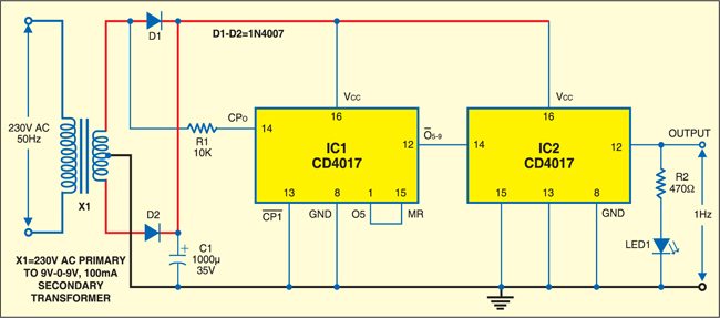
The 50Hz input signal is also taken from the secondary winding of transformer X1 and fed to clock pin 14 of decade counter CD4017 (IC1), which is wired as a divide-by-5 counter via resistor R1. IC1 now produces 10Hz output at its pin 12, which is further given to the clock pin of another IC CD4017 (IC2), wired as a divide-by-10 decade counter. The output of IC2 can be seen as a 1Hz clock pulse on the screen of the oscilloscope and also as one flash per second on LED1 connected in series with the output load (resistor R2).

Construction & testing
After construction and testing, enclose the circuit in a suitable cabinet. This circuit can be easily assembled on a veroboard.
The article was first published in April 2007 and has recently been updated.