


Auto makers have been gradually switching to light emitting diode (LED) lighting for automotive headlamps because of its features such as high efficiency and long service life. In addition, from a safety perspective, applications of LED-driven daylight/daytime running lights (DRLs) for vehicles are spreading in many states.
The purpose of the daytime running lights controller circuit presented here is to activate DRLs on any lighting that uses LED and/or incandescent bulb in a vehicle. Before attempting to construct this circuit, remember that, you cannot directly hook up this circuit to any circuit that is controlled by the CANbus system in a vehicle. For example, if the parking lights of your vehicle are CANbus-controlled, the DRL circuit cannot be plugged to the parking-light circuit for DRL function.
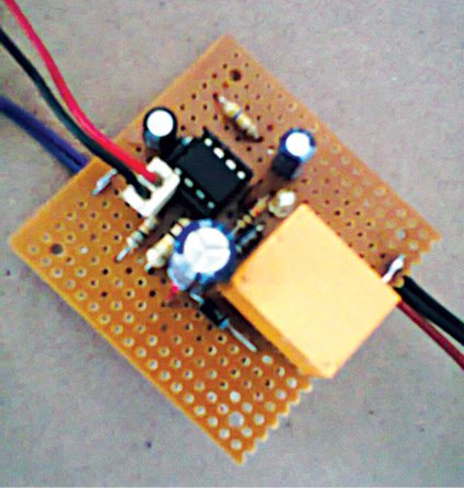
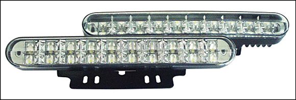
But, if the fog-light circuit is not controlled by CANbus, then you can connect the DRL circuit to it. Author’s prototype of the daytime running lights controller is shown in Fig. 1.
Daytime running lights controller circuit
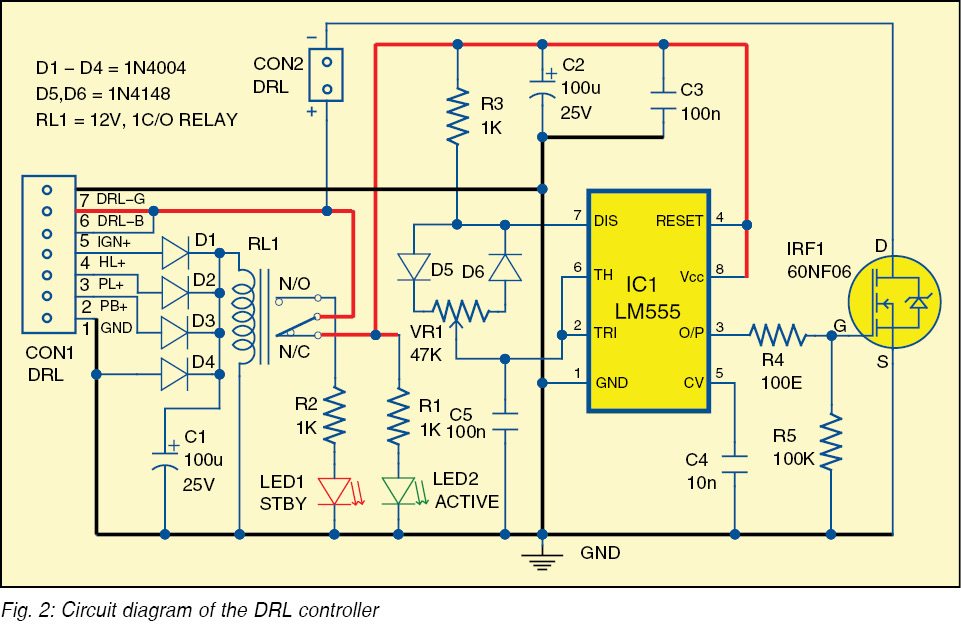
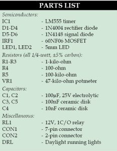
Fig. 2 shows the circuit diagram of the daytime running lights controller. It is built around timer NE555 (IC1), MOSFET 60NF06 (IRF1), 12V, 1C/O relay (RL1), DRLs and a few other components.
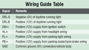
There are seven wires that come out of the circuit. The first connection (DRL-B and DRL-G) you will make is to the DRLs. These are the main wires that will make the bumper DRLs turn on when you start the vehicle (these will light up at start).
Connect DRL-B and DRL-G wires from the circuit directly to the DRLs at the bumper. The circuit activates when it senses ignition voltage. It does so by getting a signal from the main wire (IGN+) and the positive supply wire that runs from the circuit to the ignition-switched +12V power line. GND is main ground connection, and it must be connected directly to the negative battery (0V) terminal or the body of the vehicle.
You might have to extend the wire, if it does not reach the battery, by running sufficient length of the automotive wire from the circuit to the negative terminal of the battery. If you want the DRLs to switch off when you turn your headlights and/or parking lights on, connect HL+ and PL+ to the existing headlight and parking-light wires, respectively.
Wire connection PB+ is optional; you do not have to connect it unless you want the DRLs to work with the parking brake (hand brake). The potmeter (VR1) can be used to adjust the brightness of DRLs as per requirement. Note that, you can modify the circuit’s default Set Off mode as per your choice, or according to the relevant law of the land.
The default Set Off mode of the DRL is given below:
IGN+ (ignition): ON→DRL: ON
HL+/PL+/PB+ (headlight/park light/hand
brake): ON→DRL: OFF
The circuit is a simple pulse-width modulator (PWM) built around the ubiquitous 555 timer. User-controllable PWM output from IC1 is used to switch on the DRLs through MOSFET 60NF06 (as MOSFET on DRL ground is connected to circuit ground).
Here, 555 is configured as astable and, hence, it is possible to have completely-independent control of charge and discharge times of the timing capacitor by using two external diodes (D5 and D6). The 12V 1C/O electromagnetic relay in the circuit is used to enable/disable the DRL controller circuitry, as per status of the headlight/parking light/hand brake. LED1 indicates standby and LED2 indicates the active modes of the DRL controller.
Note:
Driving the MOSFET from a noisy line calls for a small series gate resistor close to the MOSFET. Using a low-value 100-ohm resistor (R4) between the MOSFET driver and MOSFET gate terminal dampens down any ringing oscillations caused by lead inductance and gate capacitance, which can otherwise exceed the maximum voltage allowed on the gate terminal. Also, using pull-down 100k resistor (R5) from the gate to the source of the MOSFET is a good practice.
Download PCB and component layout PDFs: click here
Construction and testing
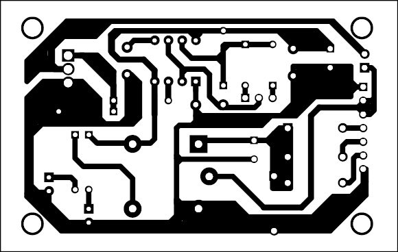
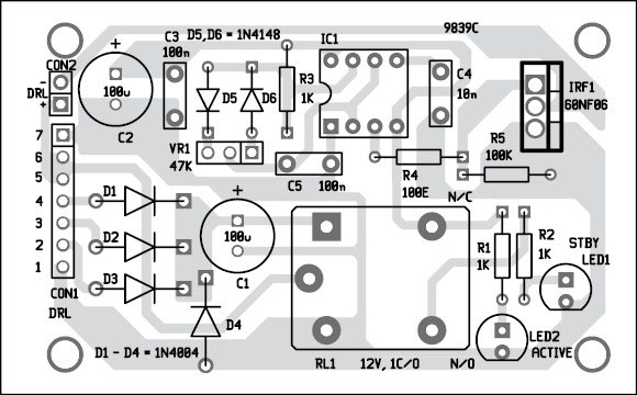
A single side PCB for the daytime running lights controller circuit is shown in Fig. 4 and its component layout in Fig. 5. Enclose the circuit in a suitable small box with connectors CON1 and CON2 on the front side to connect the seven control signals and the DRL.
After assembling the circuit, refer to the wiring guide table before connecting these to the PCB board.
Panel-mount the input and output interface, as required.

not working
when i connect the battery no led lights shows power not stand by nor active led works…nothing ……
It’s double tested by me, and at EFY Labs. Retest your prototype!
I’s working. I have one question, how to test If the battery is above 13,5 V, and then turn the drl on?
Thank you
How will connecting the headlights or parking lights as shown result in the drls turning off?
hey can we use 12v ledstrip light as drl
Do you have a part# for the potmeter and the relay for this project?