This digitally controlled precision amplifier circuit is similar to the circuit of the attenuator. Gain of up to 100 can be achieved in this configuration, which is useful for signal conditioning of low output of transducers in millivolt range.
Digitally controlled precision amplifier circuit
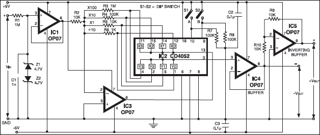
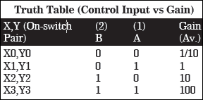
The gain selection resistors R3 to R6 can be selected by the user and can be anywhere from 1 kilo-ohm to 1 meg-ohm. Trimpots can be used for obtaining any value of gain required by the user. The resistor values shown in the circuit are for decade gains suitable for an auto-ranging DPM.
Resistor R1 and capacitor C1 reduce ripple in the input and also snub transients. Zeners Z1 and Z2 limit the input to ±4.7V, while the input current is limited by resistor R1. Capacitors C2 and C3 are the power supply decoupling capacitors.

Circuit operation
Op-amp IC1 is used to increase the input impedance so that very low inputs nare not loaded on measurement. The user can terminate the inputs with resistance of his choice (such as 10 meg-ohm or 1 meg-ohm) to avoid floating of the inputs when no measurement is being made.
IC5 is used as an inverting buffer to restore polarity of the input while IC4 is used as buffer at the output of CD4052, because loading it by resistance of value less than 1 meg-ohm will cause an error. An alternative is to make R9=R10=1 megohm and do away with IC4, though this may not be an ideal method.
Gains greater than 100 may not be practical because even at gain value of 100 itself, a 100μV offset will work out to be around 10 mV at the output (100μV x 100). This can be trimmed using the offset null option in the OP07, connecting a trimpot between pins 1 and 8, and connecting wiper to +5V supply rails. For better performance, use ICL7650 (not pin compatible in place of OP07 and use ±7.5V instead of ±5V supply.
Eight steps for gain or attenuation can be added by using two CD4051 and pin 6 inhibit on CD4051/52. More steps can be added by cascading many CD4051, or CD4052, or CD4053 ICs, as pin 6 works like a chip select.
Some extended applications of this circuit are given below.
- Error correction in transducer amplifiers by correcting gain.
- Auto-ranging in DMM.
- Sensor selection or input type selection in process control.
- Digitally preset power supplies or electronic loads.
- Programmable precision mV or mA sources.
- PC or microcontroller or microprocessor based instruments.
- Data loggers and scanners.
The article was first published in January 2007 and has recently been updated.