


 Presented here is a simple pedometer (Distance Counter) circuit. It measures the distance covered by you while walking. It may not work very well for running!
Circuit and working
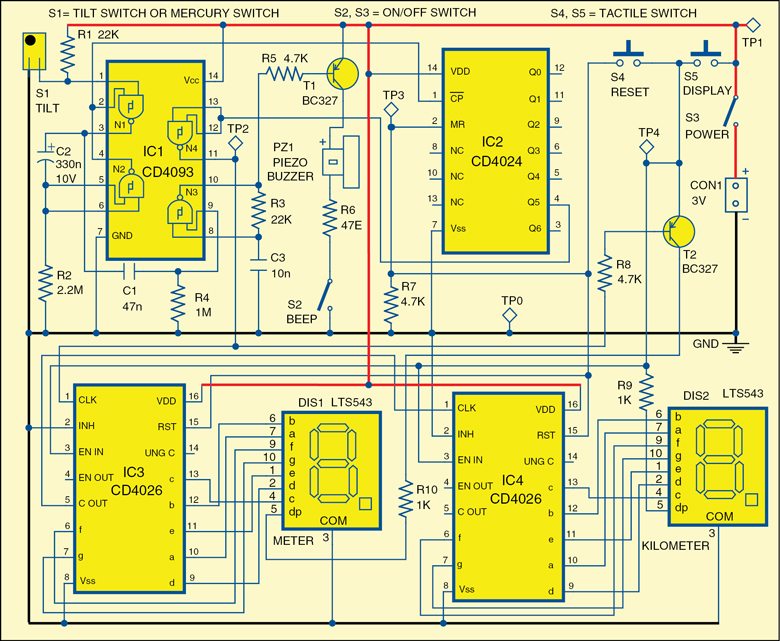
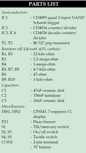
Fig. 1 shows a circuit diagram of the distance counter. The circuit is built around quad 2-input Schmitt trigger CD4093 (IC1), CMOS ripple carry binary counter/divider CD4024 (IC2), decade counter/divider CD4026 (IC3 and IC4), two transistors BC327 (T1, T2) and some other components.
Download PCB and component layout PDFs: click here
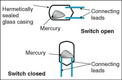
Gates N1 and N2 of IC1 form a monostable multivibrator that receives trigger input from tilt or mercury switch S1. When you lift your foot up and touch the ground back during walking, the mercury inside the switch makes a contact with its two metallic leads as shown in Fig. 2. This makes the current to flow between the metallic leads and a pulse is generated at pin 4 of IC1.

This pulse is fed to pin 1 of IC2 that produces a divide-by-64 counter. Its output is given to inputs of gate N4 of IC1 and the output of N4 is fed to the base of transistor T2 through resistor R8. Transistor T2 drives the decimal point segment of common cathode 7-segment display (DIS1).
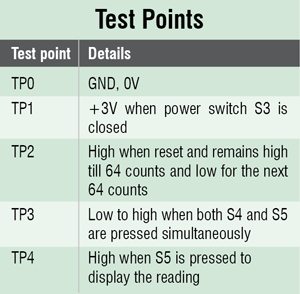
IC3 and IC4 are configured as decade counters to drive the 7-segment displays DIS1 and DIS2, respectively. Switch S4 resets these two counters and switch S5 enables DIS1 and DIS2 displays.
Transistor T1 drives the piezo buzzer (PZ1), which beeps after every two steps (one stride), provided switch S2 is closed. DIS1 and DIS2 displays indicate the distance covered in metre (m) and kilometre (km) units, respectively.
 Generally, walking step of each individual is slightly different. Here, we assume that a single step is 78cm long, which is the average. According to this, 64 strides equal 100m (that is, 2×0.78×64=99.84m or 100m (approx.)) or 128 steps equal 100m.
DIS1 increments the digit after every 100m distance. That is, DIS1 displays 1 when distance covered is 100m and 2 when distance covered is 200m, and so on. After digit 9 in DIS1, DIS2 increments from 0 to 1 digit. The decimal point (dot) of DIS2 always glows to indicate separation of kilometre from the metre unit.
 To save battery power consumption, DIS1 and DIS2 displays illuminate only when you push S5. If you want to reset the counter circuit, both switches S4 and S5 must be pressed simultaneously.
If you want to continuously illuminate DIS1 and DIS2 displays, remove switch S5 and connect the junction of S4 and emitter of transistor T2 to 3V.
Construction and testing
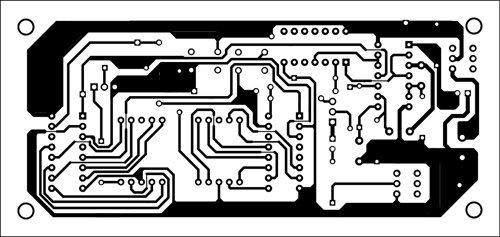
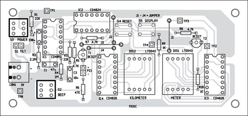
A single-side PCB for the distance counter is shown in Fig. 3 and its component layout in Fig. 4.
Mount DIS1 to the right of DIS2 as shown in the PCB so that you get proper readings. For example, if DIS2 shows 5 and DIS1 shows 2, the reading will be 5km and 200m. It means the distance travelled is 5200m.
After assembling the circuit on PCB, enclose it in a suitable plastic case so that you can keep it in your trouser’s pocket or attach it to your belt.
Use 2-pin connector CON1 for 3V battery in the PCB. Also, fix switches S2 through S5 on the front side of the case.
The author is an electronics hobbyist.

Is any programming required?
No, you do not need any programming.
Instead of mercury switch you can place normal switch is it correct or not
is there any video regarding this project ?if anyone have plzz mail it
Any video in this project
Is it possible to increase the number of numbers and the seven-Segments screen