

A traditional lock can pose problems if the keys required to unlock them get lost. In such a case, they will need to be replaced for security purposes. Same applies for an RFID-based lock that is dependent on the availability of an RFID tag.
So today, we will design a smart lock that does not need any keys or RFID tags. Instead, it uses Bluetooth to directly connect to our phone and simply requires a password to gain access.
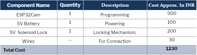
Bill Of Material
Let’s start our project by shopping the following components:

In addition to these, you will require an FTDI programmer or an Arduino IDE to upload the program to the ESP32 Cam and a relay to control the solenoid lock.
Pre-Requisites
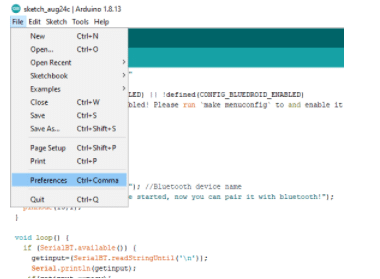
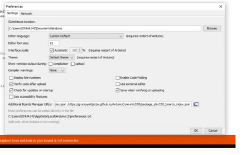
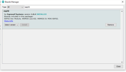
First, we need to add the ESP32 board to the Arduino IDE. To do so, go to File → Preferences and paste the given URL in the Board Manager URL option. After that click OK and then go to Tools → Search ESP32 and then install the board. After a successful installation, we are now ready to code.

https://dl.espressif.com/dl/package_esp32_index.json
https://arduino.esp8266.com/stable/package_esp8266com_index.json
Coding
Now we can start our coding. Here we use the Bluetooth of the ESP32 Cam as Bluetooth serial. So first we need to include the Bluetooth serial library in the code.
Next, we will create a string “pasw” where the password for our lock will be stored, and a new string where the password entered by the user will be saved. After that we will set the pin number of the lock to control the solenoid.

Next, we will set the serial baud rate and also the Bluetooth serial name for using SerialBT.begin().
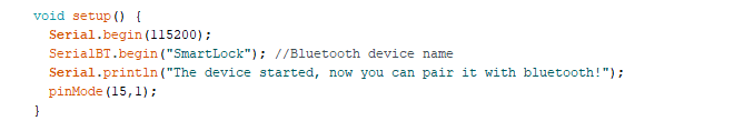
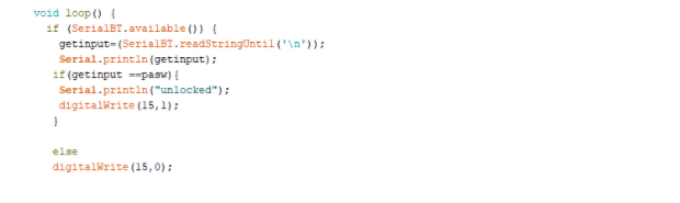
After this, create a loop function for checking the availability of Bluetooth serial input given by the user. If the input is available, then we will read and save it in an empty string variable named get input. An If condition will try to create a match between the entered password and the set password. Whenever found correct, it will initiate unlock otherwise nothing will happen and the lock will remain intact.
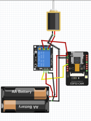
Connection
Now connect the ESP32 Cam with FTDI, program it, and then connect all the components as shown in the circuit diagram.
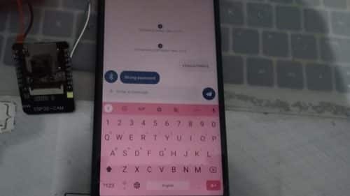
Testing
Now install the Bluetooth terminal app or any Bluetooth serial supported app in Android and switch ON the phone’s Bluetooth. Then connect to Bluetooth of ESP32 and enter the correct password to unlock the lock.